
SLIDE 1
10/11/15 1
MOBILE COMPUTING
CSE 40814/60814 Fall 2015
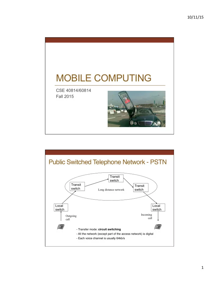
Public Switched Telephone Network - PSTN
Local switch Local switch Transit switch
Outgoing call Incoming call
Transit switch Transit switch
Long distance network
- Transfer mode: circuit switching
- All the network (except part of the access network) is digital
- Each voice channel is usually 64kb/s