Lecture 2: Links and Signaling CSE 123: Computer Networks Chris - - PDF document

lecture 2 links and signaling
SMART_READER_LITE
LIVE PREVIEW

Lecture 2: Links and Signaling CSE 123: Computer Networks Chris - - PDF document

Lecture 2: Links and Signaling CSE 123: Computer Networks Chris Kanich Project 1 out Today, due Mon 7/11 Lecture 2 Overview Signaling Types of physical media Shannons Law and Nyquist Limit Encoding schemes Clock recovery


slide-1
SLIDE 1

1

Lecture 2: Links and Signaling

CSE 123: Computer Networks Chris Kanich Project 1 out Today, due Mon 7/11

CSE 123 – Lecture 1: Course Introduction 2

Lecture 2 Overview

 Signaling

 Types of physical media  Shannon’s Law and Nyquist Limit

 Encoding schemes

 Clock recovery  Manchester, NRZ, NRZI, etc.

 A lot of this material is not in the book  Caveat: I am not an EE Professor

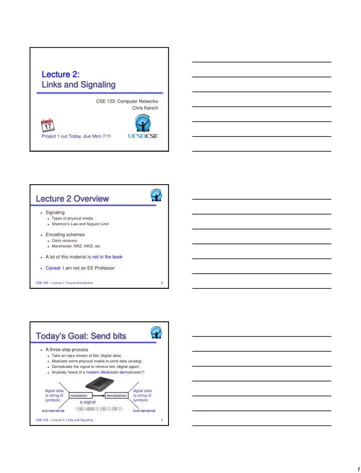
Today’s Goal: Send bits

 A three-step process

 Take an input stream of bits (digital data)  Modulate some physical media to send data (analog)  Demodulate the signal to retrieve bits (digital again)  Anybody heard of a modem (Modulator-demodulator)?

CSE 123 – Lecture 2: Links and Signaling 3

digital data (a string of symbols) digital data (a string of symbols)

a signal

modulation demodulation 0101100100100 0101100100100

slide-2
SLIDE 2

2

A Simple Signaling System

CSE 123 – Lecture 2: Links and Signaling 4

Signals and Channels

 A signal is some form of energy (light, voltage, etc)

 Varies with time (on/off, high/low, etc.)  Can be continuous or discrete  We assume it is periodic with a fixed frequency

 A channel is a physical medium that conveys energy

 Any real channel will distort the input signal as it does so  How it distorts the signal depends on the signal

CSE 123 – Lecture 2: Links and Signaling 5

Channel Challenges

 Every channel degrades a signal

 Distortion impacts how the receiver will interpret signal

CSE 123 – Lecture 2: Links and Signaling 6

B freq response ideal actual

slide-3
SLIDE 3

3

Channel Properties

 Bandwidth-limited

 Range of frequencies the channel will transmit  Means the channel is slow to react to change in signal

 Power attenuates over distance

 Signal gets softer (harder to “hear”) the further it travels  Different frequencies have different response (distortion)

 Background noise or interference

 May add or subtract from original signal

 Different physical characteristics

 Point-to-point vs. shared media  Very different price points to deploy

CSE 123 – Lecture 2: Links and Signaling 7

Copper

CSE 123 – Lecture 2: Links and Signaling 8

Typical examples

 Category 5 Twisted Pair

10-1Gbps 50-100m

 Coaxial Cable

10-100Mbps 200m

twisted pair copper core insulation braided outer conductor

  • uter insulation

coaxial cable (coax)

Fiber Optics

CSE 123 – Lecture 2: Links and Signaling 9

 Typical examples

 Multimode Fiber

100Mbps 2km

 Single Mode Fiber

100-2400Mbps 40km

Cheaper to drive (LED vs laser) & terminate Longer distance (low attenuation) Higher data rates (low dispersion)

slide-4
SLIDE 4

4

Common Link Speeds

 Copper based off of old phone-line provisioning

 Basic digital service was 64-Kbps ISDN line  Everything else is an integer multiple

» T-1 is 24 circuits 24 * 64 = 1.544 Mbps » T-3 is 28 T-1s, or 28 * 1.544 = 44.7 Mbps

 Optical links based on STS standard

 STS is electrical signaling, OC is optical transmission  Base speed comes from STS-1 at 51.84 Mbps  OC-3 is 3 * 51.84 = 155.25 Mbps

 Move to asymmetric link schemes

 Your service at home is almost surely ADSL / Cable

CSE 123 – Lecture 2: Links and Signaling 10

Wireless

 Widely varying channel bandwidths/distances  Extremely vulnerable to noise and interference

CSE 123 – Lecture 2: Links and Signaling 11

Freq (Hz) 104 106 108 1010 1012 1014

AM Coax Microwave Satellite Fiber FM Twisted Pair TV

Radio UV Microwave IR Light

Spectrum Allocation

CSE 123 – Lecture 2: Links and Signaling 12

Time (min) Frequency (Hz)

 Policy approach forces spectrum to be allocated like a fixed spatial resource (e.g. land, disk space, etc)  Reality is that spectrum is time and power shared  Measurements show that fixed allocations are poorly utilized0

Whitespaces, anyone?

slide-5
SLIDE 5

5

Two Main Tasks

 First we need to transmit a signal

 Determine how to send the data, and how quickly

 Then we need to receive a (degraded) signal

 Figure out when someone is sending us bits  Determine which bits they are sending

 A lot like a conversation

 “WhatintheworldamIsaying” – needs punctuation and pacing  Helps to know what language I’m speaking

CSE 123 – Lecture 2: Links and Signaling 13

The Magic of Sine Waves

 All periodic signals can be expressed as sine waves

 Component waves are of different frequencies

 Sine waves are “nice”

 Phase shifted or scaled by

most channels

 “Easy” to analyze

 Fourier analysis can tell

us how signal changes

 But not in this class…

CSE 123 – Lecture 2: Links and Signaling 14

Carrier Signals

 Baseband modulation: send the “bare” signal

 E.g. +5 Volts for 1, -5 Volts for 0  All signals fall in the same frequency range

 Broadband modulation

 Use the signal to modulate a high frequency signal (carrier).  Can be viewed as the product of the two signals

CSE 123 – Lecture 2: Links and Signaling 15

Amplitude

Signal Carrier Frequency

Amplitude

Modulated Carrier

slide-6
SLIDE 6

6

Forms of Digital Modulation

CSE 120 – Lecture 1: Course Introduction 16 Input Signal Amplitude Shift Keying (ASK) Frequency Shift Keying (FSK) Phase Shift Keying (PSK)

Why Different Schemes?

CSE 123 – Lecture 2: Links and Signaling 17

 Properties of channel and desired application

 AM vs FM for analog radio

 Efficiency

 Some modulations can encode many bits for each symbol

(subject to Shannon limit)

 Aiding with error detection

 Dependency between symbols… can tell if a symbol wasn’t

decoded correctly

 Transmitter/receiver Complexity

Intersymbol Interference

 Bandlimited channels cannot respond faster than

some maximum frequency f

 Channel takes some time to settle

 Attempting to signal too fast will mix symbols

 Previous symbol still “settling in”  Mix (add/subtract) adjacent symbols  Leads to intersymbol interference (ISI)

 OK, so just how fast can we send symbols?

CSE 123 – Lecture 2: Links and Signaling 18

slide-7
SLIDE 7

7

Speed Limit: Nyquist

 In a channel bandlimited to f, we can send at

maximum symbol (baud) rate of 2f without ISI

CSE 123 – Lecture 2: Links and Signaling 19

Multiple Bits per Symbol

 OK, but why not send multiple bits per symbol

 E.g., multiple voltage levels instead of just high/low  Four levels gets you two bits, log L in general  Could we define an infinite number of levels?

 Channel noise limits bit density

 Intuitively, need level separation  Only get log(S/2N) bits per symbol

 Can combine this observation with Nyquist

 C < 2 B log(S/2N) in a perfect channel, but…

CSE 123 – Lecture 2: Links and Signaling 20

Noise Matters: Shannon’s Law

 Shannon considered noisy channels and derived

C = B log (1 + S/N)

 Gives us an upper bound on any channel’s

performance regardless of signaling scheme

 Old school modems approached this limit

 B = 3000Hz, S/N = 30dB = 1000  C = 3000 x log(1001) =~ 30kbps  28.8Kbps, anyone?

CSE 123 – Lecture 2: Links and Signaling 21

slide-8
SLIDE 8

8

Sampling at the Receiver

 Need to determine correct sampling frequency

 Signal could have multiple interpretations

CSE 123 – Lecture 2: Links and Signaling 22

Signal

1 1 1 1

Signal

1 1

Which of these is correct?

Nyquist Revisited

 Sampling at the correct rate (2f) yields actual signal

 Always assume lowest-frequency wave that fits samples

 Sampling too slowly yields aliases

CSE 123 – Lecture 2: Links and Signaling 23

The Importance of Phase

 Need to determine when to START sampling, too

CSE 123 – Lecture 2: Links and Signaling 24

slide-9
SLIDE 9

9

Clock Recovery

 Using a training sequence to get receiver lined up

 Send a few, known initial training bits  Adds inefficiency: only m data bits out of n transmitted

 Need to combat clock drift as signal proceeds

 Use transitions to keep clocks synched up

 Question is, how often do we do this?

 Quick and dirty every time: asynchronous coding  Spend a lot of effort to get it right, but amortize over lots of

data: synchronous coding

CSE 123 – Lecture 2: Links and Signaling 25

Asynchronous Coding

CSE 123 – Lecture 2: Links and Signaling 26

 Encode several bits (e.g. 7) together with a leading

“start bit” and trailing “stop bit”

 Data can be sent at any time  Start bit transition kicks of sampling intervals  Can only run for a short while before drifting

Example: RS232 serial lines

 Uses two voltage levels (+15V, -15V), to encode

single bit binary symbols

 Needs long idle time – limited transmit rate

idle start 1 1 1 0 0 0 0 stop idle

  • 15

+ +15

Time Voltage

CSE 123 – Lecture 2: Links and Signaling 27

Courtesy Robin Kravets

slide-10
SLIDE 10

10

Synchronous Coding

 Asynchronous receiver phase locks each symbol

 Takes time, limiting transmission rates

 So, start symbols need to be extra slow

 Need to fire up the clock, which takes time

 Instead, let’s do this training once, then just keep sync

 Need to continually adjust clock as signal arrives  Ever hear of Phase Lock Loops (PLLs) ?

 Basic idea is to use transitions to lock in

CSE 123 – Lecture 2: Links and Signaling 28

Non-Return to Zero (NRZ)

Signal to Data

 High

 1

 Low

Comments

 Transitions maintain clock synchronization  Long strings of 0s confused with no signal  Long strings of 1s causes baseline wander

» We use average signal level to infer high vs low

 Both inhibit clock recovery

Bits 1 1 1 1 1 1 1 NRZ

Courtesy Robin Kravets

29 CSE 123 – Lecture 2: Links and Signaling

Non-Return to Zero Inverted (NRZI)

 Signal to Data

 Transition

 1

 Maintain

 Comments

 Solves series of 1s, but not 0s

Bits 1 1 1 1 1 1 1 NRZ NRZI

30

Courtesy Robin Kravets

CSE 123 – Lecture 2: Links and Signaling

slide-11
SLIDE 11

11

 Signal to Data

 XOR NRZ data with senders clock signal  High to low transition

 1

 Low to high transition

 Comments

 Solves clock recovery problem  Only 50% efficient ( ½ bit per transition)  Still need preamble (typically 0101010101… trailing 11 in Ethernet)

Bits 1 1 1 1 1 1 1 NRZ Clock Manchester

Manchester Encoding

31

Courtesy Robin Kravets

CSE 123 – Lecture 2: Links and Signaling

4B/5B (100Mbps Ethernet)

Goal: address inefficiency of Manchester encoding, while avoiding long periods of low signals

Solution:

 Use five bits to encode every sequence of four bits  No 5 bit code has more than one leading 0 and two trailing 0’s  Use NRZI to encode the 5 bit codes  Efficiency is 80%

0000 11110 0001 01001 0010 10100 0011 10101 0100 01010 0101 01011 0110 01110 0111 01111 1000 10010 1001 10011 1010 10110 1011 10111 1100 11010 1101 11011 1110 11100 1111 11101 4-bit 5-bit 4-bit 5-bit 32 CSE 123 – Lecture 2: Links and Signaling

Summary

 Two basic tasks: send and receive

 The trouble is the channel distorts the signal

 Transmission modulates some physical carrier

 Lots of different ways to do it, various efficiencies

 Receiver needs to recover clock to correctly decode

 All real clocks drift, so needs to continually adjust  The encoding scheme can help a lot

CSE 123 – Lecture 2: Links and Signaling 33

slide-12
SLIDE 12

12

For Next Class

 Read 2.3  Log into piazzza & gradesource; let me know if you

have problems

 Get started on Project 1!

CSE 123 – Lecture 2: Links and Signaling 34