
SLIDE 1
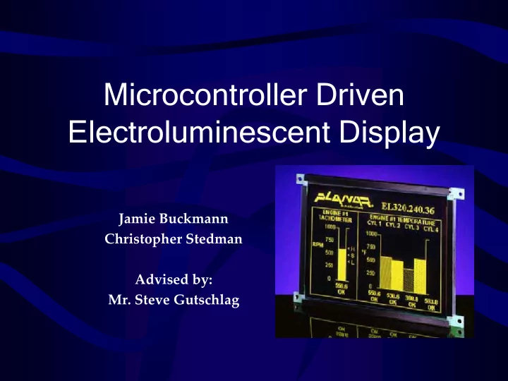
Microcontroller Driven Electroluminescent Display
Jamie Buckmann Christopher Stedman Advised by:
- Mr. Steve Gutschlag
Microcontroller Driven Electroluminescent Display Jamie Buckmann - - PowerPoint PPT Presentation
Microcontroller Driven Electroluminescent Display Jamie Buckmann Christopher Stedman Advised by: Mr. Steve Gutschlag Outline Project Summary Functional Description System Block Diagrams Software Completed Tasked Results
Jamie Buckmann Christopher Stedman Advised by:
Ignition Signal Front Tire Sensor Oil Pressure Neutral Coolant Temperature O2 Sensor Keypad Electroluminescent Display Data
Decoding Logic
ADC0808 A/D (Block 6)
Analog Inputs
Signal Conditioning (Block 8)
Conditioned Analog Signal
Data Bus
Interrupt Signal to Microprocessor EOC IN[0:7] A B C
A0 A1 A2
OE ALE START CLK Vref+ Vref- +5V 0V
AMD-80C31 Microcontroller (Block 1) Ignition Signal (RPM) Front Tire Sensor Coolant Temperature Oil Pressure HM62256 Static RAM (Block 5)
A 8:15
Decoding Logic (Block 2) SED-1330 LCD Controller (Block 3)
Decoding Logic
ADC0808 A/D (Block 6)
Decoding Logic
Signal Conditioning (Block 8)
Conditioned Analog Signal
O2 Sensor
Keypad
Electroluminescent Display (Block 4) Neutral MM74C923 Keypad Encoder (Block 7)
AD & Com
80C31 Microcontroller with External Program Memory, Data Memory, & Latch (Block 1) Ignition Signal Front Tire Sensor Oil Pressure Neutral Data Bus Address Bus RD WR Port 1 & Port 3
A (8:15)
(Block 2) LCD Controller Chip Select A/D Chip Select/ Control Signals Keypad Chip Select 500 kHz Square Wave for A/D 10 MHz Clock
RD WR
(Block 3) RD WR RES A0 XD0-XD3 XECL XSCL LP WF YDIS YD YSCL VR/W VCE VA0-VA14 VD0-VD7 From Decoder
AD[0:7]
CS
LCD Controller
(Block 3) RD WR RES A0 XD0-XD3 XECL XSCL LP WF YDIS YD YSCL VR/W VCE VA0-VA14 VD0-VD7 From Decoder
AD[0:7]
CS
LCD Controller
(Block 3) RD WR RES A0 XD0-XD3 XECL XSCL LP WF YDIS YD YSCL VR/W VCE VA0-VA14 VD0-VD7 From Decoder
AD[0:7]
CS
0000 FFFF 8000 7FFF A000 9FFF Keyboard A/D LCD Controller Program & Memory Space C000
Start Declare global variables Declare pointers (P1.7) = 0 Wait for 5 ms (P1.7) = 1 Initialize Screen Set character start address to 0000h Set graphic start address to 1000h Write spaces to all addresses in character layer Write blanks to all addresses in graphics layer Display screen End
Start
Address = Address +1 (Display value) = FF hex (11111111) ? Last address in tachometer box ? Previous address (Display value) = 0 Shift (Display value) right (Display value) = (Display value) OR 80h Write (Display value) down 10 times
End no yes yes no