
SLIDE 1
LED Back Light Cooling for Display
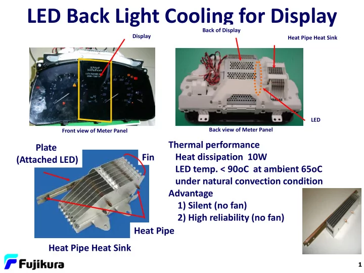
Front view of Meter Panel Back view of Meter Panel Display Back of Display Heat Pipe Heat Sink LED
Heat Pipe Heat Sink Fin Heat Pipe Plate (Attached LED) Thermal performance Heat dissipation 10W LED temp. < 90oC at ambient 65oC under natural convection condition Advantage 1) Silent (no fan) 2) High reliability (no fan)
1