
SLIDE 1
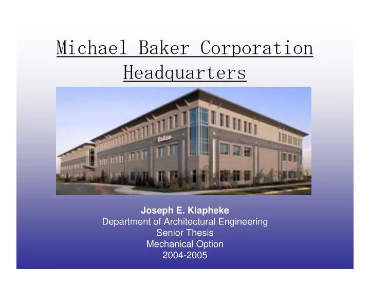
Michael Baker Corporation Headquarters
Joseph E. Klapheke Department of Architectural Engineering Senior Thesis Mechanical Option 2004-2005
Michael Baker Corporation Headquarters Joseph E. Klapheke - - PowerPoint PPT Presentation
Michael Baker Corporation Headquarters Joseph E. Klapheke Department of Architectural Engineering Senior Thesis Mechanical Option 2004-2005 Building Overview The building is currently part of proposed 6 building business park.
Joseph E. Klapheke Department of Architectural Engineering Senior Thesis Mechanical Option 2004-2005
building business park.
and a parking garage.
glass curtain wall, a metal roof cornice and punched window openings.
daylight.
100,000 square feet in open office space.
and increase productivity
ran under a 2” raised floor.
Corporation Headquarters Location: next door to the Pittsburgh International Airport Flagship of the Airside Business Park Development
Traditional Overhead VAV system In open office space, 2”raised floor system and movable partitions for easy renovation and remodeling. 525 tenants in about 100,000 square feet of office space. Flexibility is key.
1.5 cfm/sf is used to supply the building throughout the day. Excess energy costs
heat for A.M. warm-up with 50% 4” pleated filters.
leaves the air-handlers and experiences no more than 5.25” of loss.
The interior zones have cooling-only VAV boxes at about 1/1500 sq. ft. The perimeter zones have fan powered VAV boxes and electric reheat at about 1/1000 sq. ft. There are around 34 zones per floor.
respectively.
cfm/area or air changes (whichever is the most demanding)
a space due to stratification
mixed space
bacteria growth
mixed air conditions.
currently uses as much as 1.8 cfm/sf to ventilate the air.
system can deliver a more conformable, higher quality air supply.
will use about 1.0 cfm/sf.
using a UADS.
With a UADS, you can use a range from 62 F to 68 F. This redesign will be at 62 F.
redesigned building were analyzed.
$ per square foot
ductwork and $1.7 million for the redesign similarly.
cost for the current building is $114 thousand and $110 thousand for the redesign.
estimated costs for the current building is $28 thousand and the redesign is $15 thousand.
construction cost workouts out to be about $520,000.
Means.
foot.
UADS are still relatively new to most construction managers and they will likely bid higher to account for mistakes in construction.
necessary requirements to serve its occupants effectively.
lower construction and operating costs and improving indoor air quality.
The tenants can change the location of the diffusers to suit the building’s office furniture. The tenants can also change the rate of air flow leaving the diffusers.
Baker Corporation Headquarters.
system for there electrical and telecommunication cabling and connections.
floor has to have 18” of clearance.
since all now there will be only 1/3 to 1/2 the ductwork and about the same terminal units.
negligible.
connected to 480Y/277 Volt 3-phase panels. 2 per floor. 1 at 4 Watts, 200 amps the
connections.
Watts, 200 amps and the other at 208Y/120 Volts 3-phase, 4 Watts, 150 amps.
months working on this project:
Corporation Headquarters as my thesis and for all the mechanical information I needed.
including the costs of the building.
my time here.
Hi Mom!!!!
mention…you all made this special for me one way or another. Best of luck.