Local Area Networks and Medium Access Control Protocols Multiple - - PDF document

local area networks and medium access control protocols
SMART_READER_LITE
LIVE PREVIEW

Local Area Networks and Medium Access Control Protocols Multiple - - PDF document

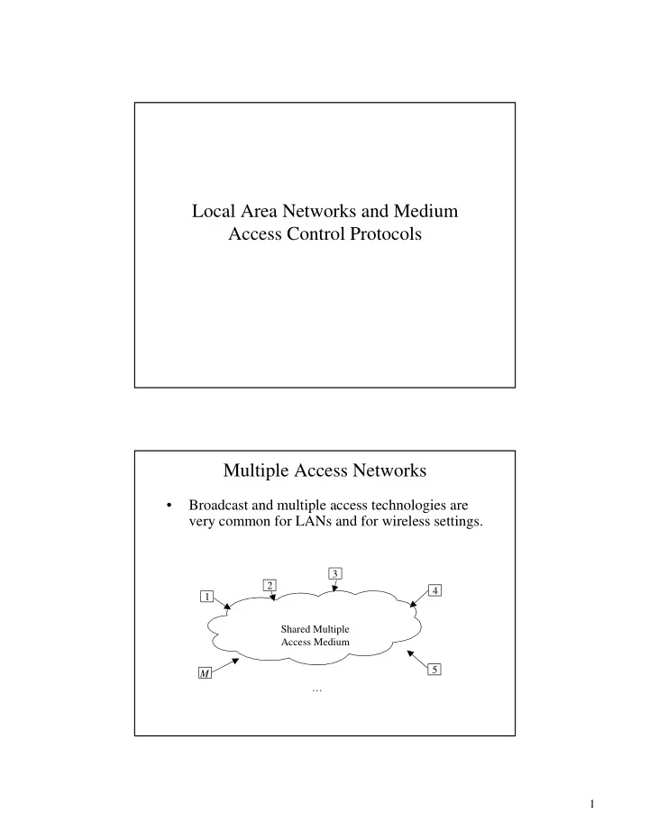
Local Area Networks and Medium Access Control Protocols Multiple Access Networks Broadcast and multiple access technologies are very common for LANs and for wireless settings. 3 2 4 1 Shared Multiple Access Medium 5 M 1


slide-1
SLIDE 1

1

Local Area Networks and Medium Access Control Protocols Multiple Access Networks

  • Broadcast and multiple access technologies are

very common for LANs and for wireless settings.

1 2 3 4 5 M Shared Multiple Access Medium …

slide-2
SLIDE 2

2

Multiple Access Communication: Examples

Satellite Channel

= fin = fout

Multidrop telephone lines

Inbound line Outbound line

Examples (2)

Ring networks Multitapped Bus

slide-3
SLIDE 3

3

Examples (3)

Wireless LAN

Multi-Access Protocols

  • Protocols that resolve the resolution problem

dynamically are called Multiple-Access (Multi- Access) Protocols

  • Contention Protocols resolve a collision after it
  • ccurs. These Protocols execute a collision

resolution protocol after each collision.

  • Collision-free Protocols ensure that a collision

never occurs.

slide-4
SLIDE 4

4

Evolution of Contention Protocols

Developed for Univ. of Hawaii packet radio network Start transmission only at fixed times (slots) CSMA = Carrier Sense Multiple Access Start transmission only if no transmission is

  • ngoing

CD = Collision Detection Stop ongoing transmission if a collision is detected

Aloha Slotted Aloha CSMA CSMA/CD

Contention Protocols

  • ALOHA Protocols

– (Pure) Aloha – Slotted Aloha

  • CSMA (Carrier Sense Multiple Access)

– Persistent CSMA – Non-persistent CSMA – CSMA/CD: Carrier Sense Multiple Access with Collision Detection (used in Ethernet)

  • Etc…
slide-5
SLIDE 5

5

(Pure) ALOHA

  • Topology:

– Multiple transmitters (stations) share same medium.

  • Aloha protocol:

– Whenever station has data, it transmits immediately – Whenever a collision occurs, it is treated as transmission error, and frame is retransmitted. – Sender backs off for some random time after collision before it retransmits.

Collisions in Pure ALOHA

1,1 1,2 1,3 Station 1 2,1 2,2 Station 2 Station 3 3,1 3,2 Broadcast channel

Transmission Time (F) Complete Collision Partial Collision

slide-6
SLIDE 6

6

Collisions and Vulnerable Period

  • A frame (dark frame) collides whenever another

transmission begins in the vulnerable period of the frame.

  • Vulnerable period has length of 2 frame times.

frame

Vulnerable Period of red frame

F F

Frame which collides with start of red frame Frame which collides with end of red frame

Slotted ALOHA

  • Slotted Aloha Protocol

– Time is divided into discrete time intervals (=slots) – A station can transmit only at the beginning of a frame

  • As a consequence:

– Frame either completely or do not collide at all – Vulnerable period = 1 frame time

slide-7
SLIDE 7

7

Collisions in Pure ALOHA

1,1 1,2 1,3 Station 1 2,1 2,2 Station 2 Station 3 3,1 3,2 Broadcast channel

Transmission Time (F) Complete Collision Partial Collision

Performance of ALOHA

  • What is the maximum throughput of the ALOHA protocol?
  • Notation:

S Throughput: Expected number of successful transmission per time unit G Offered Load: Expected number of transmission and retransmission attempts (from all users) per time unit.

  • Normalization:

– Frame transmission time is 1 => maximum throughput is 1

slide-8
SLIDE 8

8

Modeling Assumptions

  • Normalization: All frames have a fixed length of one

time unit.

  • Infinite user population
  • Offered load is modeled as a Poisson process with

rate G: Prob[k packets are generated in t frame times] =

( )

tG k

e k Gt

× !

Throughput of ALOHA

  • Relation between throughput and offered load:

S = G * Prob[frame suffers no collision]

ALOHA Broadcast Channel ALOHA Broadcast Channel collisions S G Successful transmission New transmissions

slide-9
SLIDE 9

9

Performance of (pure) ALOHA

  • Prob[frame suffers no collision]

= Prob[no other frame is generated during the vulnerable period of this frame] = Prob[no frame is generated during a 2-frame a period] =

  • Throughput in ALOHA:

( )

G G

e e G

2 2

! 2

− −

= ×

G

e G S

2 −

× =

Results: Maximum Achievable Throughput

  • Take derivative and set
  • Maximum is attained at G = 0.5
  • We obtain:
  • Note: That is 18% of channel capacity!

= ∂ ∂ G S 184 . 2 1 5 .

1 max

= = × =

e e s

slide-10
SLIDE 10

10

Performance of Slotted ALOHA

  • Derivation is analogous to (pure) ALOHA:

S = G * Prob[frame suffers no collision]

  • Prob[frame suffers no collision]

= Prob[no other frame is generated during a vulnerable period] = Prob[no frame is generated during 1 frame period] =

  • Total throughput in Slotted ALOHA:
  • Achievable Throughput:

( )

G G

e e G

1 1

! 1

− −

= ×

G

e G S

× = 37 . 1

1 max

= = =

e e s

Comparison of ALOHA and Slotted ALOHA

0.05 0.1 0.15 0.2 0.25 0.3 0.35 0.4 0.01563 0.03125 0.0625 0.125 0.25 0.5 1 2 4 8

Ge-G Ge-2G G S

0.184 0.368

slide-11
SLIDE 11

11

CSMA – Carrier Sense Multiple Access

  • Improvement over ALOHA protocol:

– If stations have carrier sense capability (stations can test the broadcast medium for ongoing transmission), and – If stations only transmit if the channel is idle, – Then many collisions can be avoided

  • Note: This improves ALOHA only in cases with

small delay bandwidth products. Why?

CSMA – Carrier Sense Multiple Access

  • CSMA protocol

– A station that wishes to transmit listens to the medium for an ongoing transmission – Is the medium busy?

  • Yes: Station backs off for a specified period
  • No: Station transmits

– If a sender does not receive an acknowledgement after some period, it assumes that a collision has occurred. – After a collision a station backs off for a certain (random) time and retransmits.

slide-12
SLIDE 12

12

CSMA - Variations

  • Variations of CSMA protocol
  • Each variant specifies what to do if the medium is

found busy:

– Non-persistent CSMA – 1-persistent CSMA – p-persistent CSMA

Non-Persistent CSMA

  • 1. If the medium is idle, transmit immediately
  • 2. If the medium is busy, wait a random amount of

time and Repeat Step 1.

  • Random back-off reduces probability of collisions.
  • Wasted idle time if the back-off time is too long.
  • May result in long access delays.
slide-13
SLIDE 13

13

1-Persistent CSMA

  • 1. If the medium is idle, transmit immediately
  • 2. If the medium is busy, continue to listen until

medium becomes idle, and then transmit immediately.

  • What if two stations want to transmit when channel

is busy?

p-Persistent CSMA

  • 1. If the medium is idle, transmit with probability p,

and delay for one time unit with probability (1-p) (time unit = length of propagation delay)

  • 2. If the medium is busy, continue to listen until

medium becomes idle, and then go to Step 1.

  • 3. If transmission is delayed by one time unit,

continue with Step 1.

  • Good trade-off between non-persistent and 1-

persistent CSMA.

slide-14
SLIDE 14

14

How to Select Probability p ?

  • Assume that N stations have a packet to send and the

medium is busy.

  • Expected number of stations that will attempt to

transmit once the medium becomes idle: N * p

  • If N * p > 1, then a collision is expected to occur

(with retransmission, and so more collisions)

  • Therefore: Network must make sure that N * p < 1,

where N is the maximum number of stations that can be active at a time.

Comparison of CSMA Strategies

channel busy constant or variable delay ready Non-persistent: Transmit if idle;

  • therwise delay and try again

1-persistent: Transmit as soon as channel goes idle. If collision, back off and try again p-persistent: Transmit as soon as channel goes idle, with probability

  • p. Otherwise, delay one slot and

repeat process.

slide-15
SLIDE 15

15

Comparison of ALOHA and CSMA

  • Load vs. Throughput (very small delay-bandwidth product)

CSMA/CD

  • CSMA has an inefficiency:

– If a collision occurred, the channel is unstable until colliding packets have been fully transmitted

  • CSMA/CD overcomes this as follows:

– While transmitting, the sender is listening to medium for

  • collision. Sender stops if collision has occurred.
  • Note:

– CSMA: Listen Before Talking – CSMA/CD: Listen While Talking

slide-16
SLIDE 16

16

Operation CSMA/CD

  • Generic CSMA/CD Protocol:

– Use one of the CDMA persistence algorithms (non- persistent, 1-persistent, p-persistent) for transmission. – If a collision is detected during transmission, cease transmission and transmit a jam signal to notify other stations of collision. – After sending the jam signal, back off for a random amount of time, then start to transmit again.

Collision Detection in CSMA/CD

Figure 6.7

A transmits at t = 0

Distance d meters tprop = d / ν seconds A B

B transmits before t = tprop and detects collision shortly thereafter

A B A B

A detects collision at t = 2 tprop

To detect a collision, in the worst case, it takes twice the maximum propagation delay of the medium.

slide-17
SLIDE 17

17

CSMA/CD: Restrictions

  • Packet should be twice as long as time to detect a

collision (2 * max. propagation delay)

  • Otherwise, CSMA/CD does not have an advantage
  • ver CSMA
  • Example: Ethernet

– Ethernet requires a minimum packet size and restricts the maximum length of the medium. – Question: What is the minimum packet size in a 10Mbit/sec network with a maximum length of 500 meters?

Exponential Backoff Algorithm

  • Ethernet uses an exponential backoff algorithm to

determine when a station can retransmit after a collision. Algorithm:

Set “slot time” equal to 2a After first collision, wait 0 or 1 slot times. After i-th collision, wait random number between 0 and 2i-1 time slots. Do not increase random number range if i=10. Give up after 16 collisions

slide-18
SLIDE 18

18

Performance of CSMA/CD

  • Parameters and assumptions:

a : end-to-end propagation delay 1 : packet transmission time (normalized) N: Number of stations

  • Time can be thought of as being divided in

contention intervals and transmission intervals.

  • Contention intervals can be thought of as being

slotted with slot length of 2a (roundtrip propagation delay).

Performance of CSMA/CD

  • Contention slots end in a collision
  • Contention interval is a sequence of contention slots
  • Length of a slot in contention interval is 2a
  • Probability that a station attempts to transmit in a

slot is P

frame frame frame contention interval contention slot

slide-19
SLIDE 19

19

Performance of CSMA/CD

  • Derivation of maximum throughput of CSMA/CD

– Let A be the probability that some station can successfully transmit in a slot. We get: – In the above formula, A is maximized when P=1/N. Thus:

1 1 1

) 1 ( ) 1 ( 1

− −

− × × = − × ×       =

N N

P P N P P N A

1

) 1 1 (

− =

N

N A

Performance of CSMA/CD

Prob[contention interval has a length of j slots] = Prob[1 successful attempt] * Prob[j-1 unsuccessful attempts] =

  • The expected number of slots in a contention interval is then

calculated as:

1

) 1 (

− ×

j

A A A A A j

j j

1 ) 1 (

1 =

− × ×

∞ = −

slide-20
SLIDE 20

20

Performance of CSMA/CD

  • Calculate the maximum efficiency of CSMA/CD

with usual formula:

A a 2 1 1 Interval Contention Average Time Frame Time Frame Overhead Time Frame Time Frame + = + = +

LAN -- Overview

  • Almost all local

area networks use a multiple access channel.

  • Lan technologies

differ in the control protocol for the access to the channel (MAC)

  • MAC protocols are

implemented as a sublayer of the Data Link Layer.

Network layer Network layer 802.2 Logical link layer Data link layer Physical layer 802.3 802.5 802.11 others Physical layer IEEE 802 OSI LLC MAC

slide-21
SLIDE 21

21

Logical Link Layer

  • Similar to HDLC
  • Provides SAP to higher layers
  • Provides different services

– Acknowledged connectionless service – Unacknowledged connectionless service – Connection-oriented service

  • Framing
  • Error Control
  • Addressing

Standards for MAC Protocols

  • Bus Networks:

– IEEE 802.3 CSMA/CD (=Ethernet) – IEEE 802.4 Token Bus

  • Ring Networks:

– IEEE 802.5 Token Ring – ANSI FDDI

  • Dual Bus Networks

– IEEE 802.6 DQDB

  • Tree Networks

– IEEE 802.14 HFC (Cable Modems)

slide-22
SLIDE 22

22

IEEE 802 Architecture

  • The IEEE 802 Architecture is a family of standards

for LANs (local area networks) and MANs (metropolitan area networks)

  • Organization of IEEE 802 Protocol Architecture

– Higher Layers: 802.1 Higher Layer Interfaces – Logical Link Control: 802.2 LLC – MAC Layers: 802.3 CSMA/CD 802.4 Token Bus 802.5 Token Ring Etc.

IEEE 802 LAN Standard

slide-23
SLIDE 23

23

IEEE 802 LAN Standard IEEE 802.3 (CSMA/CD)

  • Bus Topology
  • Generally referred to as “Ethernet”
  • Based on CSMA/CD
  • Exponential back-off after collisions
  • Data rate: 2Mbps – 1Gbps
  • Maximum cable length dependent on the data rate

transceiver

slide-24
SLIDE 24

24

802.3 Frame Format

  • Preamble is sequence of 7 bytes (“10101010” for each byte).

Helps receiver synchronize with bit pattern before frame is received.

  • At 10 Mbps, a frame must be at least 46 byte long.

Otherwise, station may not detect collision with its own transmission.

  • Maximum frame size is set to 1500 byte of data, minimum

frame size is set to 512 bits.

Ethernet

  • Several physical layer configurations are possible for 802.3

LANs.

  • The following notation is used to denote the configuration
slide-25
SLIDE 25

25

Ethernet

  • Speed: 10 Mbps
  • Standard: 802.3
  • Physical layers:

– Used today:

  • 10Base-T

10Mbps Twisted Pair

  • 10Base2

(Thin Ethernet) 10Mbps thin coax cable

– Used in the past

  • 10Base5

(Thick Ethernet) 10Mbps thick coax cable

– Analog version

  • 10Broad36

10Mpbs on coax cable using analog signaling

Bus Topology

  • 10Base5 and 10Base2 Ethernets have a bus topology
slide-26
SLIDE 26

26

Repeaters

  • Maximum length of a segment is 500m (10Base5)

and 200m (10Base2)

  • The maximum span can be extended by connecting

segments via repeaters

  • Repeaters do not isolate collisions

Star Topology

  • With 10Base-T, stations are connected to a hub in a star

configuration.

  • Distance of a node to the hub must be <= 100m.
slide-27
SLIDE 27

27

Fast Ethernet

  • “Fast Ethernet” = Ethernet at 100Mpbs rates
  • Standard: IEEE 802.3u

– 100Base-T4 (100 Mbps over telephone-grade twisted pair) – 100Base-TX (100 Mbps over Category 5 twisted pair) – 100Base-FX (100 Mbps over Fiber Optic)

  • 100Base-X schemes have two physical links, one for

receiving and one for transmitting, each at 10o

  • Mpbs. A station can send an transmit at the same

time (full-duplex)

  • 100 Base-T4 operates in half-duplex mode

Gigabit Ethernet

  • Data rate is 1 Gbps = 1000 Mbps
  • Standard: IEEE 802.3z
  • Physical layers:

– 1000Base-SX (short wave laser over multimode fiber) – 1000Base-LX (long-wave laser over single mode fiber and multimode fiber) – 1000Base-?? (twisted pair)

slide-28
SLIDE 28

28

Ring-Based LANs

Ring interface To station From station

Ring-Based LANs

  • The ring can be thought of as a series of bit-wise

repeaters, each connected via a unidirectional transmission link.

  • All arriving data is copied into a 1-bit buffer and

then copied out again (1-bit delay)

  • Data in the buffer can be modified before

transmission

  • The ring interface can be in one of the following

states:

– Listen State – Transmit State – Bypass State

slide-29
SLIDE 29

29

States of the Ring Interface

  • Listen State: Incoming

bits are copied to output with 1-bit delay

  • Transmit State: write

data to the ring

  • Bypass State: Idle

station does not incur bit-delay

Ring-Based LANs

  • If a frame has traveled once around the ring, it is retired by

the sender.

  • Ring-based LANs have a simple acknowledgement scheme:
  • Each frame has one bit for acknowledgement.
  • If the destination receives the frame it sets the bit to 1.
  • Since the sender will see the returning frame, it can tell if the

frame was received correctly.

slide-30
SLIDE 30

30

“Length” of a Ring

  • The length of a ring LAN, measured in bits, gives

the total number of bits that can be in transmission

  • n the ring at a time.
  • Note: Frame size is not limited to the “length” of the

ring since entire frame may not appear on the ring at

  • ne time. (Why?)
  • Bit length = propagation delay * length of ring * data rate +
  • No. of stations * bit delay at repeater

“Length” of Ring: Example

  • Calculate the length of the following ring LAN:

– 3 km ring – 1 Mbps data rate – 5 usec/km propagation speed – 20 stations with 1 bit delay each

  • Bit length =
slide-31
SLIDE 31

31

Ring-Based LANs

  • Advantages:

– Can achieve 100% utilization – No collisions – Can achieve deterministic delay bounds – Can be made efficient at high speeds

  • Disadvantages:

– Long delays due to bit-delays

  • Solution: Bypass state eliminates bit-delay at idle station

– Reliability problems

  • Solution 1: Use a wire center
  • Solution 2: Use a second ring (in opposite direction)

Ring-Based LANs: Wire Center (802.5)

slide-32
SLIDE 32

32

Ring-Based LANs: Use a Second Ring Token Ring MAC Protocol (802.5)

  • In order to transmit a station must catch a free token.
  • The station changes the token from free to busy.
  • The station transmits its frame immediately followig

the busy token.

  • After a complete transmission of a frame, the sender

station inserts a new free token after the busy token has returned to the station.

  • Only one station can transmit at a time. If a station

releases a free token, the next station downstream can capture the token

slide-33
SLIDE 33

33

Transmission in a Token Ring

  • Sender

looks for free token.

Transmission in a Token Ring

  • Sender changes

free token to busy token and appends data to the token.

slide-34
SLIDE 34

34

Transmission in a Token Ring

  • Receiver recognizes

that it is the destination of the frame

  • Receiver copies

frame to station

  • Note: Frame also

returns to sender

Transmission in a Token Ring

  • Receiver recognizes

that it is the destination of the frame

  • Receiver copies

frame to station

  • Note: Frame also

returns to sender

slide-35
SLIDE 35

35

Transmission in a Token Ring

  • Sender generates

free token when it is done transmitting (Note: the busy token has returned).

Properties of the 802.5 Token Ring

  • No collision of frames
  • Full utilization of bandwidth is feasible
  • Transmission can be regulated by controlling access

to token

  • Recovery protocols are needed if token is not

handled properly, e.g. token is corrupted, station does not change to “free”, etc.

slide-36
SLIDE 36

36

Token Format / Data Format IEEE 802.5 Frame Format

  • One 3-byte token circulates if all stations are idle

AC = “PPPTMRRR” where “PPP” Priority fields “RRR” Reservation fields “T” Indicates “Token” or “Data frame”

  • SD,ED:

Start/End delimiter of a frame

  • FC:

Identifier type of a control frame

  • FS:

Contains address recognized bit (A bit) and frame copied bit (C bit)

– Receiver sets A=1 when frame arrives – Receiver sets C=1 when frame has been copied

slide-37
SLIDE 37

37

Priority of Transmission in 802.5

  • Eight levels of priorities
  • Priorities handled by 3-bit priority field and 3-bit

reservation field

  • Define:

– Pm = priority of the message to be transmitted – Pr = token priority of received token – Rr = reservation priority of received token

Priority Transmission in 802.5

  • 1. A station wishing to transmit a frame with priority

Pm must wait for a free token if Pr <= Pm

  • 2. The station can reserve a future priority-Pm token

as follows:

– If busy token comes by, the set Rr = Pm (if Rr < Pm) – If free token comes by, then set Rr = Pm (if Rr < Pm and Pm < Pr)

slide-38
SLIDE 38

38

Priority Transmission in 802.5

  • 3. If a station gets a free token, it sets the reservation

field to “0”, and leaves the priority field unchanged and transmits

  • 4. After transmission send a free token with
  • 1. Priority = max(Pr, Rr, Pm)
  • 2. Reservation = max(Rr, Pm)
  • 5. Station that upgraded the priority level of a token

must also downgrade the priority (if no one used the token)

Ring Maintenance

  • Token ring selects one station as the monitor station
  • Duties of the monitor:

– Check that there is a token – Recover ring if it is broken – Detect garbled frames – Make sure the token (24-bit) is shorter than the ring length

slide-39
SLIDE 39

39

Terms in IEEE 802.5

  • IEEE 802.5 requires to maintain a large number of

counters

  • THT: Token Holding Timer (one per station)

– Limits the time that a station can transmit (Default 10 ms)

  • TRR: Time-to-Repeat Timer (one per station)

– Limits that a station waits for return of own message (Default 2.5 ms)

  • TVX: Valid Transmission Timer (in monitor station)

– Verifies that station which accessed the token actually used it (Default: THT + TRR = 12.5 ms)

  • TNT: No-Token Timer (one per station)

– If expire, a new token is generated (Default: N*(THT+TRR))

Performance of Token Rings

  • Parameters and Assumptions
  • End-to-end propagation delay

a

  • Packet transmission time

1

  • Number of stations

N

  • Assume that each station always has a packet

waiting for transmission

  • Note: The ring is used either for data transmission or

for passing the token

slide-40
SLIDE 40

40

Performance of Token Rings

  • Define:
  • T1 = Average time to transmit a frame. Per

assumption, T1 = 1

  • T2 = Average time to pass token

2 1 1

Overhead Time Frame Time Frame Throughput Maximum T T T + = + =

Effect of Propagation Delay

  • Effect of propagation delay on

throughput

  • Case 1: a < 1 (Packet longer than

ring)

– T2 = time to pass token to next station = a/N

  • Case 2: a > 1 (Packet shorter than

ring)

– Note: Sender finishes transmission after T1=1, but cannot release the token until the token returns – T1+T2 = min(1,a) + a/N

slide-41
SLIDE 41

41

Performance of Token Rings

Illustration of Analysis (a > 1)

Performance of Token Rings

Illustration of Analysis (a < 1)

slide-42
SLIDE 42

42

Ethernet vs. Token Ring

  • Maximum throughput as a function of a

Ethernet vs. Token Ring

  • Maximum throughput as a function of N
slide-43
SLIDE 43

43

FDDI

  • Some Facts
  • FDDI = Fiber Distributed Data Interface
  • FDDI is high-speed token ring
  • Fiber-optic (dual redundant counter rotating) ring

LAN

  • Multimode fiber
  • Standardized by ANSI and ISO X3T9.5 committee
  • 100Mbps data rate
  • Maximum frame size is 4500 bytes
  • Allows up to 1000 connected stations
  • Maximum ring circumference is 200 km

FDDI

  • FDDI distinguishes 4 Service Classes

– Asynchronous – Synchronous – Immediate (monitoring and control) – Isochronous (only in FDDI-II)

slide-44
SLIDE 44

44

FDDI-Protocol Architecture

PHY coding/decoding transmit/receive data stream PHY coding/decoding transmit/receive data stream PMD conversion to optical signal PMD conversion to optical signal SMT initialization performance monitoring maintenance allocation of bandwidth configuration SMT initialization performance monitoring maintenance allocation of bandwidth configuration LLC(IEEE 802.2) Logical Link Control LLC(IEEE 802.2) Logical Link Control MAC ring access data transfer MAC ring access data transfer

SMT Station Management MAC Medium Access Control PHY Physical Layer Protocol PMD Physical Layer Medium Dependend

Dual Redundant Counter Rotating Ring

  • Second ring adds fault tolerance:
slide-45
SLIDE 45

45

Station Types: Class A Station

  • Two PHY (and onr or two MAC) entities
  • Connects to another Class A station or to a concentrator

From Last Station To Next Station

Station Types: Class B Station

  • Class B station has one PHY (and one MAC) entity
  • Connects to a concentrator

To Concentrator

slide-46
SLIDE 46

46

Station Types: Concentrator

  • Connects Class A and Class B stations into one of the counter

rotating rings.

  • Concentrator can bypass failing stations.

Topology Example

slide-47
SLIDE 47

47

FDDI Medium Access Control

  • FDDI uses a Token Ring Protocol, similar to 802.5
  • Differences of FDDI and 802.5:

– To release a token, a station does not need to wait until the token comes back after a transmission. The token is released right after the end of transmission. – In FDDI, multiple frames can be attached to the token. – FDDI has a different priority scheme.

FDDI Token Ring Protocol

  • 1. A awaits token
  • 2. A seizes token, begins

transmitting frame F1 addressed to C

slide-48
SLIDE 48

48

FDDI Token Ring Protocol

  • 3. A appends token to end of

transmission.

  • 4. C copies frame F1 as it

goes by.

FDDI Token Ring Protocol

  • 5. C continues to copy F1; B

seizes token and transmits frame F2 addressed to D.

  • 6. B emits token; D copies

F2; A absorbs F1

slide-49
SLIDE 49

49

FDDI Token Ring Protocol

  • 7. A lets F2 and token pass;

B absorbs F2

  • 8. B lets token pass

Frame and Token Format

  • SD

Starting Delimiter

  • FC

Frame Control (type of frame)

  • DA

Destination Address

  • SA

Source Address

  • FCS

Frame Check Sequence (CRC)

  • ED

End Delimiter

  • FS

Frame Status

  • Totel Frame length <= 4500 byte

Preamble Preamble SD SD FC FC DA DA SA SA FCS FCS ED ED FS FS Info Info General Frame Format Preamble Preamble SD SD FC FC Token Frame Format

slide-50
SLIDE 50

50

Timed Token Protocol

  • FDDI has a timed token protocol which determines

how long a station can transmit

  • Each station has timers to measure the time elapsed

since a token was last received

  • Target Token Rotation Time (TTRT)

– Value of TTRT is negotiated during initialization (default is 8ms) – Set to the maximum desired rotation time

Parameters of Timed Token Protocol

  • Station Parameters
  • TRT : Token Rotation Time

– Time of last rotation of the token – If TRT < TTRT, then token is “early”, asynchronous traffic can be transmitted – If TRT > TTRT, then token is late, asynchronous traffic cannot be transmitted

  • THT : Token Holding Time

– Controls the time that a station may transmit asynchronous traffic.

  • fi : Percentage of tht TTRT that is allocated for

synchronous traffic at Station i

slide-51
SLIDE 51

51

Timed Token Protocol

  • If a station received the token, it sets

– THT := TRT – TRT := TTRT – Start TRT timer

  • If the station has waiting synchronous frames, then

transmit up to the time TTRT + fi (with Σifi <= 1)

  • If the station has asynchronous traffic

– Start THT timer – Until timer expires, transmit asynchronous traffic.

Timed Token Protocol

  • Transmission is not interrupted if THT expires

during a transmission.

  • If a station does not utilize its maximum

transmission time (that is, THT), the next station can use it.

slide-52
SLIDE 52

52

Analysis of FDDI: Synchronous Traffic

  • Each transmission can transmit synchronous traffic

for up to time TTRT + fi (with Σifi <= 1)

  • If Σifi = 1, the maximum throughput of synchronous

traffic is 100%.

  • One can show that the maximum delay unti la frame

is completely transmitted is

Maximum Access Delay <= 2 * TTRT

Analysis of FDDI: Asynchronous Traffic

  • Parameters

D Ring Latency N Number of active sessions (all heavily loaded) T Value of TTRT

  • Assumption: No

synchronous traffic

slide-53
SLIDE 53

53

Analysis of FDDI: Asynchronous Case

  • From the example we see:

– Cycle in a system has a length of: nT + D – Time in a cycle used for transmission: n(T-D)

  • We obtain for the maximum throughput for

asynchronous traffic :

  • … and for the maximum access delay for

asynchronous traffic:

Analysis of FDDI: Example

  • Number of stations:

16

  • Length of fiber:

200km

  • Speed of signal:

5ms/km

  • Delay per station:

1ms/station

  • TTRT:

5msec

  • Ring Latency D = (20km)*(5msec/km) +

+ (16 stations) * 1 msec/station = = 0.12msec

slide-54
SLIDE 54

54

Analysis of FDDI: Comparison

  • Synchronous traffic:

– Max. Throughput = 100% – Max. Access Delay = 2*5ms = 10ms

  • Asynchronous traffic:

– Max. Throughput = 16(5-0.12)/(16*5+0.12)=97.5% – Max. Access Delay = 5(16-1)+2*0.12=75.24ms

FDDI: Throughput vs. TTRT

  • Typical FDDI

– 20 stations (single MAC) – 4km ring

  • Big FDDI

– 100 stations (single MAC) – 200 km ring

  • Largest FDDI

– 500 stations (dual MAC) – 200 km ring

slide-55
SLIDE 55

55

FDDI: Maximum Access Delay vs. TTRT

  • Typical FDDI

– 20 stations (single MAC) – 4km ring

  • Big FDDI

– 100 stations (single MAC) – 200 km ring

  • Largest FDDI

– 500 stations (dual MAC) – 200 km ring