? Liquid Applied Mineral wool CSPE Extruded polystyrene Built-up - - PDF document

liquid applied mineral wool cspe extruded polystyrene
SMART_READER_LITE
LIVE PREVIEW

? Liquid Applied Mineral wool CSPE Extruded polystyrene Built-up - - PDF document

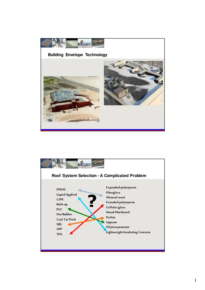
Building Envelope Technology Roof System Selection - A Complicated Problem Expanded polystyrene EPDM Fiberglass ? Liquid Applied Mineral wool CSPE Extruded polystyrene Built-up Cellular glass PVC Wood Fiberboard Hot Rubber Perlite


slide-1
SLIDE 1

1

Building Envelope Technology EPDM Liquid Applied CSPE Built-up PVC Hot Rubber Coal Tar Pitch SBS APP TPO Expanded polystyrene Fiberglass Mineral wool Extruded polystyrene Cellular glass Wood Fiberboard Perlite Gypsum Polyisocyanurate Lightweight Insulating Concrete

?

Roof System Selection - A Complicated Problem

slide-2
SLIDE 2

2

Structural Decks

Concrete

Steel Wood

Typical Roof Assembly

  • Structural deck.
  • Insulation.
  • Membrane.

The structural deck and the insulation combine to create the substrate platform f or the roof membrane.

Substrate Platform

slide-3
SLIDE 3

3

The Foundation Of The Roof Membrane

Roof Insulation Substrate Platform Functions

  • Resist applied loads both in-

plane and out of plane.

slide-4
SLIDE 4

4

Substrate Platform Functions

  • Resist applied loads both in-

plane and out of plane.

  • Prov ide the most continuous

surf ace possible for roof membrane placement.

Substrate Platform Functions

  • Resist applied loads both in-

plane and out of plane.

  • Prov ide the most continuous

surf ace possible for roof membrane placement.

  • Prov ide dimensional stability:

– Under extreme temperature

f luctuations.

– In contact with moisture.

slide-5
SLIDE 5

5

Substrate Platform Functions

  • Resist applied loads both in-

plane and out of plane.

  • Prov ide the most continuous

surf ace possible for roof membrane placement.

  • Prov ide dimensional stability:

– Under extreme temperature

f luctuations.

– In contact with moisture.

  • Prov ide slope-to-drain.
slide-6
SLIDE 6

6

Substrate Platform Functions

  • Resist applied loads both in-

plane and out of plane.

  • Prov ide the most continuous

surf ace possible for roof membrane placement.

  • Prov ide dimensional stability:

– Under extreme temperature

f luctuations.

– In contact with moisture.

  • Prov ide slope-to-drain.
  • Prov ide heat f low resistance.

Substrate Platform Functions

  • Resist applied loads both in-plane

and out of plane.

  • Prov ide the most continuous

surf ace possible for roof membrane placement.

  • Prov ide dimensional stability:

– Under extreme temperature

f luctuations.

– In contact with moisture.

  • Prov ide slope-to-drain.
  • Prov ide heat f low resistance.
  • Prov ide f ire resistance.
slide-7
SLIDE 7

7

Substrate Platform Functions

  • Resist applied loads both in-plane

and out of plane.

  • Prov ide the most continuous

surf ace possible for roof membrane placement.

  • Prov ide dimensional stability:

– Under extreme temperature

f luctuations.

– In contact with moisture.

  • Prov ide slope-to-drain.
  • Prov ide heat f low resistance.
  • Prov ide f ire resistance.
  • Prov ide wind resistance.

Substrate Platform Functions

  • Additional f unctions not related to the roof membrane include

contributions to:

– Sound reduction. – Building env elope sustainability. – LEED credits.

slide-8
SLIDE 8

8

1880s 1920s 1930s 1940s 1950s 1960s 1970s 1980s 1990s 2000s 2010s

Mineral Fiber Wood Fiber Board Lightweight Insulating Concrete Fiberglass Cellular Glass Perlite Board XEPS MEPS PUR/ISO Composites Phenolic Insulation

EPS

Pre-Insulation Era Insulation Era

Ev en the most basic membrane sy stems perf ormed well.

1880s 1920s 1930s 1940s 1950s 1960s 1970s 1980s 1990s 2000s 2010s

Mineral Fiber Wood Fiber Board Lightweight Insulating Concrete Fiberglass Cellular Glass Perlite Board XEPS MEPS PUR/ISO Composites Phenolic Insulation

EPS

Pre-Insulation Era Insulation Era

New high R-v alue insulating sy stems were introduced. Problems with traditional roof membranes arose.

slide-9
SLIDE 9

9

Thermal Expansion – Concrete / High Mass Thermal Expansion – Polyisocyanurate / Low Mass

slide-10
SLIDE 10

10

The Effect Of COE

  • Mov ement due to higher COE
  • f substrate material

(insulation) creates strain at board joints.

  • The mov ement is caused by the

inherent instability of some insulation products.

  • The ef f ect of this movement is

distributed throughout the roof by the number of joints presented with board stock insulation. 100 squares of 4 x 8 foot board material has more than a half mile (3,650 linear feet) of board joints!

Joints ?

slide-11
SLIDE 11

11

Lightw eight Insulating Concrete Rigid Insulation

Roof Insulation Systems

Metal Deck Structural Slab Existing Asphaltic Membrane

Re-Roofing vs New Construction

slide-12
SLIDE 12

12

Existing Building Renovations Placement of Slurry and EPS Insulation

slide-13
SLIDE 13

13

Existing Drain Elevations Roof Deck / Reroof Platform

slide-14
SLIDE 14

14

Lightw eight insulating concrete top fill Lightw eight insulating concrete slurry Expanded poly sty rene (EPS) insulation board

Components of a LWIC System

Lightweight insulating concrete top fill. Molded expanded polystyrene insulation board. Lightweight insulating concrete slurry.

Components of a NVS System

  • Insulperm expanded polystyrene

insulation board.

  • High insulation value.

– R=4 per inch

  • Stable R-value over time.
  • No blowing agents.
  • Not affected by water.
  • Lightweight material to build slope to

drain.

– 1 inch thickness = 0.1 lb / sq ft

slide-15
SLIDE 15

15

Lightw eight insulating concrete top fill Lightw eight insulating concrete slurry

Components of a LWIC System

Lightweight insulating concrete top fill. Molded expanded polystyrene insulation board. Lightweight insulating concrete slurry.

Definition – Lightweight Insulating Concrete (LWIC)

“A concrete made with or without aggregate in addition to Portland cement, water and air to f orm a hardened material hav ing an ov en dry unit weight of 50 pcf or less.” A merican Concrete Institute A CI 523.1 R-06 Guide for Cast-in-Place Low-Density Concrete

slide-16
SLIDE 16

16

Structural Lightweight Concrete

  • What is Structural Lightweight Concrete?

– Structural concrete (normal weight)

  • 150 pcf dry density / 3,500 psi

– Structural lightweight concrete (SLC)

  • 100 pcf dry density / 2,500 psi

– Lightweight insulating concrete

  • 35 pcf dry density for NVS / 300 psi

Aggregate-Based LWIC

  • Aggregate.
  • Air entrainment.
  • Portland cement - Type I, II, or

III.

  • Water.
slide-17
SLIDE 17

17

Cellular-Based LWIC

  • Pregenerated foam.
  • Portland cement - Type I, II, or

III.

  • Water.

Aggregate vs. Cellular

  • Aggregate.

– 125-300 psi. – Top-fill thickness 2” (or 1”). – Drying Shrinkage. – 0.20 – 0.45 (ACI 523.1R-06). Cellular. – 200 psi. – Top-fill thickness 2”. – Drying Shrinkage. – 0.30 – 0.60 (ACI 523.1R-06).

slide-18
SLIDE 18

18

slide-19
SLIDE 19

19

slide-20
SLIDE 20

20

slide-21
SLIDE 21

21

Top Fill Finishing

slide-22
SLIDE 22

22

Attachments Methods for Roof Membrane over LWIC

Different technologies for roof membrane attachment

slide-23
SLIDE 23

23

Slope to Drain

Get the water of f the roof

Stable Insulation Value

What is long-term thermal resistance (L TTR)? L TTR is a 15-year time weighted average R-value for permeably faced polyiso, commonly used as roof insulation. L TTR represents the most advanced scientifically supported method to describe the long term thermal resistance (R-value) of polyisocyanurate foam insulation products.

slide-24
SLIDE 24

24

New values for 2014 for polyisocyanurate foam insulation products.

Stable Insulation Value

Iso R-Value For 2014

Substrate Platform Functions Thickness LTTR (2004-2013) New LTTR (2014 - ) 1 inch 6.0 5.6 1.5 inches 9.0 8.6 2 inches 12.1 11.4 3 inches 18.5 17.4 4 inches 25.0 23.6

slide-25
SLIDE 25

25

LWIC R-value is constant

  • LWIC R-value

– L

TTR is not applicable

  • Both lightweight insulating

concrete fill and molded expanded polystyrene board have thermal resistance values that do not decrease over time.

“The R-value of EPS is stable and does not change over time. The R-value performance for EPS insulation is discussed in the report. The report shows that samples of EPS insulation had no deterioration in R-value. The test results at 70° F for thermal resistance of EPS insulation samples taken from roof systems of various ages indicated no deterioration in the R-value over time. The following table compares two examples of published R-values to samples taken from actual roof decks:”

"Report on Expanded Polystyrene Insu lation for Use ASTM C 578 In Built-Up and Single Ply Roofing Systems" by Re ne M. Dupuis and Jerome G. Dees, dated August 1984.”

Stable Insulation Value

Age Density R-Value Published Initial Values At time of manufacture. 1.00 pcf 1.25 pcf 3.85 3.92 EPS Insulation Samples 13 Y ears 15 Y ears 1.28 pcf 1.09 pcf 3.94 4.07

slide-26
SLIDE 26

26

Parallel Heat Flow Concept Gap Membrane Insulation Fastener

slide-27
SLIDE 27

27

slide-28
SLIDE 28

28

Fire Resistance

Lightweight insulating concrete systems are non-combustible. UL fire resistance designs.

  • Cost ef fective roof-ceiling

designs.

slide-29
SLIDE 29

29

Wind Uplift Resistance

80 y ears of wind resistance perf ormance f or LWIC. Comprehensiv e, current FM, UL & Dade testing and approv als.

slide-30
SLIDE 30

30

Hurricane Ike Hurricanes

slide-31
SLIDE 31

31

10.01.1 Metal Deck Over Bar Joists “Metal Decks ov er bar joists were generally one

  • f two ty pes: metal deck with rigid insulation or

metal deck with lightweight insulating concrete. In each of these sy stems the metal deck was attached to the bar joists by welding or by self tapping screws. Of the two sy stem types observed, the system using lightweight concrete performed best, all

  • ther f actors considered equal.”

Documented Field Wind Performance High Mass & Low Mass Substrates

High Mass Low Mass

  • Wood.
  • Concrete.
  • Lightweight Insulating Concrete.
  • Wood fiber board.
  • Perlite board.
  • Cellular glass.
  • Extruded polystyrene.
  • Molded polystyrene.
  • Polyisocyanurate.
  • Glass fiber board.
slide-32
SLIDE 32

32

An Ancient Concept

The Mass Effect

slide-33
SLIDE 33

33

Heat is the single biggest factor in the aging of roof membranes.

The Mass Effect Think About It

  • Rigid f oam plastic board stock insulations with high R-v alues are

intended to decrease heat transf er between the interior and exterior of a building.

  • They hav e less ability to absorb and release heat than traditional

substrates such as wood and concrete.

  • Theref ore, the roof membrane is exposed to higher heat for longer

periods of time.

slide-34
SLIDE 34

34

Aging By Arrhenius Equation

Increasing the membrane temperature 18°F (10°C) doubles the aging rate, based on the Arrhenius Equation.

The Mass Effect Study: Thermocouple Placement

DensDeck/PolyisocyanurateDeck

X

Paradiene 30 / Paradiene 20 DensDeck Polyisocyanurate Metal Deck

slide-35
SLIDE 35

35

The Mass Effect Study: Thermocouple Placement

Lightweight Insulating Concrete Deck

Paradiene 30 / Paradiene 20 Lightweight Insulating Concrete EPS Metal Deck Parabase

X

The Mass Effect Study

The Mass Effect

Exposure Decks

slide-36
SLIDE 36

36

The Mass Effect Study Results

Aging By Arrhenius Equation

  • Increasing the membrane

temperature 18°F (10°C) doubles the aging rate, based

  • n the Arrhenius Equation.
  • By encapsulating rigid f oam

plastic board stock insulation in lightweight insulating concrete, lightweight insulating concrete sy stems provide both high insulating v alues and higher heat capacity.

slide-37
SLIDE 37

37

The Mass Effect Study Results

Substrate Percentage Increase In Aging In Relation To 1:6 ZIC 1:6 ZIC Aggregate (2 inches thick) Baseline (Best Performer) 1:4 ZIC Aggregate (2 inches thick) 7.2% DensDeck Cover Board (1/4-inch thick) W ith Poly iso 49.1% Perlite Cover Board (3/4-inch thick) W ith Poly iso 53.1%

The Mass Effect Study Results

slide-38
SLIDE 38

38

The Damping Effect ASHRAE Time Lag / Damping

slide-39
SLIDE 39

39

The Mass Effect

Goal – achiev e a balance of time lag(insulation) and temperature damping(thermal mass).

  • Metal deck.
  • Portland Cement.
  • EPS.

Siplast LWIC System Sustainable Components

slide-40
SLIDE 40

40

Sustainable Roofs

  • Highlights Lightweight

Insulating Concrete Roof Insulations.

– Produces low roof

membrane temperature.

– High thermal efficiency. – More stable and durable.

Structural Substrate ZIC Sy stem Roofing STC

26 ga. Corrugated Steel 2” 1:6 ZIC Above Flutes BUR/Gravel 41 26 ga. Corrugated Steel 1” Insulperm 2” 1:6 ZIC Above Insulperm BUR/Gravel 36 22 ga. Corrugated Steel 2” 1:4 ZIC On Flutes 7” Insulperm EPS 2” 1:4 ZIC Above Insulperm Paradiene 20/30 43 22 ga. Corrugated Steel 2” 1:4 ZIC On Flutes 7” Insulperm EPS 4” 1:4 ZIC Above Insulperm Paradiene 20/30 44 22 ga. Corrugated Steel 2” 1:4 ZIC On Flutes 12” Insulperm EPS 4” 1:4 ZIC Above Insulperm Paradiene 20/30 46 4-inch Structural Concrete 3” Insulperm 1 ½” NVS Concrete Above Insulperm Modified Bitumen/ Gravel 55

Sound Reduction

slide-41
SLIDE 41

41

Structural Lightweight Concrete

  • Roof ing ov er newly poured

structural lightweight concrete slabs (SLC) has become an issue f or general contractors, roofing contractors, consultants and roof ing manuf acturers.

  • This is a sequencing,

perf ormance, and liability issue f or the roof ing contractor, roof consultant, and general contractor.

  • Not a new issue.

Structural Lightweight Concrete

  • This is a sequencing,

perf ormance, and liability issue f or the roof ing contractor, roof consultant, and general contractor.

  • Not a new issue.
slide-42
SLIDE 42

42

What Is The Concern?

  • Latent moisture in newly

poured structural lightweight concrete (SLC) creates problems.

“Moisture accumulation” “Adhesion loss” “Adhesive issues” “Metal and fastener corrosion” “Insulation R-value loss”

Lightweight Insulating Concrete LEED Contribution

LEED v4

November 2013

slide-43
SLIDE 43

43

Lightweight Insulating Concrete LEED Contribution

PIMA Environmental Product Declaration

Lifecycle Design

slide-44
SLIDE 44

44

PIMA Environmental Product Declaration Life Cycle Stages of Polyiso

Lifecycle Design

718 tons (3,184 cubic y ards of solid waste) of old roof insulation debris div erted f rom the local landfill. Equals 15 rail cars this size of

  • ld roof insulation.

Dollar v alue of salvaged roof insulation: $133,600 (2007 dollars). Actual landf ill disposal f ees avoided: $29,797 (2007 dollars). Heav y vehicle transportation miles av oided: 2,120 miles / 265 gallons

  • f f uel.

Tim G. Pennigar, Project Manager, Structural Sy stems Engineering & Operations Div ision Duke University Health Sy stem.

Sustainability

slide-45
SLIDE 45

45

  • Original roof sy stem was lightweight

insulating concrete and a two-ply, torch-applied SBS-modif ied bitumen membrane, installed in 1974.

  • In the summer of 2011, test cuts

showed the existing sy stem was suitable f or a re-cov er.

  • The owner sav ed ov er $200,000 by

not remov ing the existing insulation and membrane.

Sustainability

Application is not limited by height.

slide-46
SLIDE 46

46

LWIC Solution

  • Plaza Deck
slide-47
SLIDE 47

47

LWIC Solution

slide-48
SLIDE 48

48

Thinking out of the box

  • Lightweight insulating concrete systems.
  • Phoenix Plaza, Hartf ord, Conn.

Non Roofing Applications

slide-49
SLIDE 49

49

slide-50
SLIDE 50

50

slide-51
SLIDE 51

51

slide-52
SLIDE 52

52

slide-53
SLIDE 53

53

slide-54
SLIDE 54

54

Canadian Resources Performance

slide-55
SLIDE 55

55

Lightweight Insulating Concrete Roof Insulation Systems

Innovative Roof Insulation Systems

One of the oldest, most versatile, and sustainable roof insulations on the planet