
SLIDE 1
19/11/2019 1
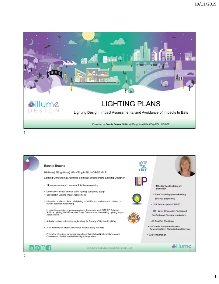
LIGHTING PLANS
Lighting Design, Impact Assessments, and Avoidance of Impacts to Bats
Presented by Bonnie Brooks BA(Hons) BEng (Hons) MSc CEng MSLL MCIBSE
Bonnie Brooks
BA(Hons) BEng (Hons) MSc CEng MSLL MCIBSE MILP Lighting Consultant (Chartered Electrical Engineer and Lighting Designer)
- 14 years experience in electrical & lighting engineering
- Undertakes interior, exterior, street lighting, daylighting design
- Specialist in Lighting Impact Assessments
- Interested in effects of not only lighting on wildlife and environment, but also on
human health and well being
- Involved in provision of various guidance documents such BCT ILP Bats and
Artificial Lighting, Bath Enterprise Zone, Guidance on Undertaking Lighting Impact Assessments
- Actively involved in industry- regional rep for Society of Light and Lighting
- Won a number of awards associated with her BEng and MSc
- Presented at various symposiums and events including Nocturnal landscapes
Conference, Wildlife and Artificial Light Symposium
- MSc Light and Lighting with
Distinction
- First Class BEng (Hons) Building
Services Engineering
- 18th Edition Update 2382-20
- 2391 Level 3 Inspection, Testing and
Certification of Electrical Installations
- JIB Qualified Electrician
- NVQ Level 3 Advanced Modern
Apprenticeship in Electrotechnical Services
- BA (Hons) Design
www.illume-design.co.uk | info@illume-design.co.uk