SLIDE 2 13.5
Sequential Logic
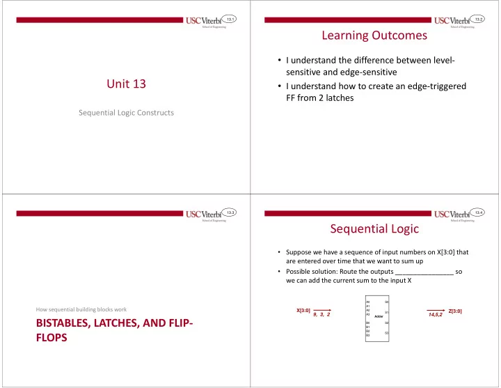
- Suppose we have a sequence of input numbers on X[3:0] that
are entered over time that we want to sum up
- Possible solution: Route the outputs back to the inputs so we
can add the current sum to the input X
_________________
_____________ to inputs and be added more than once per input number
Possible Solution
Outputs can feedback to inputs and update them sum more than once per input
A0 A1 A2 A3 B0 B1 B2 B3 S0 S1 S2 S3 Adder X0 X1 X2 X3 Z0 Z1 Z2 Z3
9, 3, 2
13.6
Sequential Logic
- Add logic at outputs to just capture and remember the new
sum until we’re ready to input the next number in the sequence
This logic should remember (i.e. sequential logic) the sum and only update it when the next number arrives
9, 3, 2
The data can still loop around and add up again (2+2=4) but if we just hold our output = 2 then the feedback loop will be broken We remember initial sum
- f 2 until input 3 arrives
at which point we’d capture & remember the sum 5. A0 A1 A2 A3 B0 B1 B2 B3 S0 S1 S2 S3 Adder X0 X1 X2 X3 Z0 Z1 Z2 Z3 13.7
Sequence Adder
- If X changes _____________ then Z should also
change once per cycle
- That is why we will use ___________________ to
ensure the outputs can only update once per cycle
A0 A1 A2 A3 B0 B1 B2 B3 S0 S1 S2 S3 4-bit Adder X0 X1 X2 X3 D
CLR
Q D Q D Q D Q Clock Y0 Y1 Y2 Y3 Z0 Z1 Z2 Z3
CLR CLR CLR
Reset
13.8
Sequence Adder
time
- The Reset (aka Clear) input on the FFs will cause Z to be initialized
to 0, but then Z can’t change until the next positive edge
- That means we will just keep adding 0 + 2 = 2
X 2 Clock 3 9 Reset Y Z 2
2 2
A0 A1 A2 A3 B0 B1 B2 B3 S0 S1 S2 S3 4-bit Adder X0 X1 X2 X3 D
CLR
Q D Q D Q D Q Clock Y0 Y1 Y2 Y3 Z0 Z1 Z2 Z3
CLR CLR CLR
Reset