
SLIDE 1
LC Detector R&D: Report from Liaisons Jan Strube (Tohoku - - PowerPoint PPT Presentation
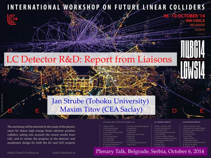
LC Detector R&D: Report from Liaisons Jan Strube (Tohoku University) Maxim Titov (CEA Saclay) Plenary Talk, Belgrade, Serbia, October 6, 2014 Push -pull Option 2 detectors: June 2013: Detailed Baseline Design (DBD) for Detectors
VERTEX: flavour tag, IP resolution (H bb, cc tt) ~1/5 rbeampipe,1/30 pixel size, ~1/10 resolution (ILC vs LHC) TRACKING: recoil mass to Higgs (e+e- ZH llX) ~1/6 material, ~1/10 resolution (ILC vs LHC); B = 3.5 – 5T CALORIMETRY: particle flow, di-jet mass resolution 1000x granularity, ~1/2 resolution (ILC vs LHC); detector coverage down to very low angle
IP 5 10 psin
3/2 (m)
ILD SiD “Push-pull Option” – 2 detectors: similar concepts / different realizations (central tracking with Si or TPC) Cost constrained design choices June 2013: Detailed Baseline Design (DBD) for Detectors
http://www.linearcollider.org/ILC/Publications/Technical-Design-Report
Key detector R&D technologies have been demonstrated with prototypes in test beams; Physics performance has been studied in full simulations
NB: incomplete list. For illustration purposes only. Many forms of Detector R&D relevant to LC:
concept groups (ILD, SiD, CLIC), which may become important for LC in future
Review of ILC R&D Efforts (http://ecfa-dp.desy.de):
May 2-3, 2012: Different R&D https://indico.desy.de/conferenceDisplay.py?confId=5800 Nov. 5, 2012: CALICE R&D https://indico.desy.de/conferenceDisplay.py?confId=6830 Jun. 10, 2013: FCAL R&D https://indico.desy.de/conferenceDisplay.py?confId=7893 Nov. 4-5, 2013: LCTPC R&D http://indico.desy.de/conferenceDisplay.py?confId=8573 Jun. 11-12, 2014: Vertex Detector R&D https://indico.desy.de/conferenceDisplay.py?confId=10026
arXiv: 1212.5127 LC-DET-2014-001
DEPFET for Belle II CMOS MAPS for STAR
…
CMOS-MAPS Initial Objective: ILC (with staged performance) applied to hadron experiments with intermediate requirements (STAR, ALICE, CBM) Prototype for PET Applications: 3x3 array of LYSO crystals with SiPMs (300 ps time resolution): TRECAM (Tumor Resection CAMera): miniaturized gamma- camera for breast cancer surgery 49 x 49 mm2 field of view LaBr3:Ce crystal optically coupled to a multi-anode photomultiplier tube
The detector R&D liaison ensures productive communication between the LCC Physics and Detectors Executive Board and detector R&D groups. The liaison is a member of the Executive Board and communicates relevant information from the Executive Board to detector R&D groups and vice versa. The liaison is in contact with all detector R&D groups relevant to linear colliders to keep track of the overall detector R&D efforts conducted or planned for linear colliders and to periodically compile summaries of the efforts.
Make areas of overlap obvious without pointing out (not an attempt to control diff. R&Ds)
mentioned in the report.
R&D efforts and the areas where they can contribute
Individual ILC / CLIC R&D Groups were asked to provide a few pages summary (5 questions):
List of collaborating institutes (contributing to the given R&D technology)
R&D Technology Participating Institutes Description / Concept Achieved Results / Milestones : Future Activities : ILC DBD or CLIC CDR Concept:
… and were asked to summarize major activities in the table:
see details in the Detector R&D Liaison Report at LCWS in Chicago (May, 2014)
documents; from text in the mail to bullet points and to 18+ dedicated pages Contributions came in many format (LaTeX, Word, PDF, emailed text, …) with varying quality of references
Currently 60+ pages + 7 pages references. Goal was ~ 70 pages.
This can be a huge benefit. We contacted Norman Graf, Frank Gaede, Akiya Miyamoto Norman agreed to coordinate with the other members of the Software and Computing Group to compile this contribution (DD4HEP, SLIC, LCFIPlus, PandoraPFA, …) Similar 5 questions to be addressed:
for reco: precision achieved
performance with more complex events, file size, …
The current layout makes it still difficult to get a quick overview. We are working on a summary tables listing collaborating institutions, milestones, future plans. This will become the main part of an executive summary for each section (not each technology).
MAPS CMOS Chronopixel 3D Time Projection Chamber for Linear Collider Highly granular calorimeters for Linear Collider Forward calorimeters for Linear Collider
“Horizontal R&D” Collaborations: Individual R&D Efforts (e.g. vertex detectors):
FPCCD SOI
A lot of R&Ds is being carried out both within the ILD/SiD and through the “horizontal R&D collaborations” In the following, selection of the recent R&D results is presented not possible to make a comprehensive review apologies if your R&D efforts are not shown this time
Inner radius~1.6cm Outer radius~ 6 cm
Low mass for tracking & vertexing
Unprecedented granularity & stable low-mass mechanical support with pulsed-power and cooling ultra-thin Si-sensors (50 m for pixel vertex detectors
Light support structures e.g. advanced endplate for TPC A complex set of highly correlated issues:
aspects and services need careful thinking in terms of material budget and power cycling, besides the usual speed/resolution/ data flow requirement Many technology choices: CPS, DEPFET, FPCCD, SOI Chronopixel, 3D, HV-CMOS (SiD-oriented) Thin-Si +Timepix, HV- CMOS (CLIC-oriented)
STAR-PXL PHYSICS RUN OF SPRING ’14 CPS validated for vertex detectors
sensor architectures developed in 0.35 μm CMOS process for ILD-VXD comply with DBD requirements
CMOS for STAR ALICE-ITS =NEW DRIVING APPLICATION OF CPS based on a better suited (180 nm) CMOS process (TDR approved by LHCC in March ’14)
1st real scale sensor prototype adapted to 10 m2 fabricated 1st test results validate architecture in 180 nm technology 2-4 times faster read-out w.r.t. 0.35 μm technology, with up to 60 % power reduction Ultrathin ladder - PLUME 0.6%X0 (0.35X0 for ILC)
CPS MAPS: Spatial Resolution and Time Stamping NEXT STEPS :
material bugdet, power-pulsing, target: bunch tagging
DEPFET R&D for ILC vertex detector in the frame work of Belle II PXD construction Pixel sensor design and auxiliary ASICs Integration to low-mass modules Latest achievement Large area thinned DEPFET sensor full system test of Belle II vertex detector segment in the DESY beam New purely LC related activities Silicon-integrated cooling channels Extension of the all-silicon module concept to the vertex forward region
Thin multi-chip ladder
test-beam (January, 2014) Micro-channel cooling Samples with micro-cooling circuits FTD mock-up:
Chronopixel design provides for single bunch- crossing time stamping (when signal exceeds threshold, time stamp provided by 14 bit bus)
Sensor capacitance larger than expected (because of design rules)
Six different sensor designs: Deep and shallow nwells and variations on design Main problem of large sensor capacitance due to 90 nm design rules has been solved 4 out of the 6 options are acceptable for ILC applications (1 – 9.04 fF, 2 – 6.2 fF, 3 – 2.73 fF, 4/5 - 4.9 fF, 6 – 8.9 fF; opt. 1,6 are not accept.)
design based on minimum ionizing track efficiency.
55Fe results for 6 sensor options:
1 – the same design as prototype 2; 2 & 3 – violate TSMC design rules – granted waiver; 4 & 5 – “natural transistors”, allowed by design rules, with gate connected to source and drain; 6 – same, as 5, but gate connected to external bias.
Prototype 3
material budget is 3D integrated circuits: Fermilab 3D-IC MPW Run for HEP (2010): 3 chips VICTR(CMS),VIP(ILC),VIPIC(x-ray)
Vertical Integrated pixel (VIP) chip for ILC:
stamping
192x192 array
VIPIC with bumps VICTR with top sensor and interposer
36,864 pixels
to silicon wafer
metal contact to the sensor
Wafer-wafer bond Chip-wafer bond
Test beams with new readout ASICs
CCPDv3+CLICpix Timepix3 in AIDA telescope (CERN PS-T9)
Sensor and r/o simulations
TCAD simulation
sensor Allpix Geant4 simulation
Mechanics and cooling: validation of simulations
1:1 VTX mockup under construction
Ultra-thin sensors
hit resolution
TPC with MPGD-Readout spatial resolution < 100 m @ 4T
(“Asian”)
pixel readout); GEM + pixel readout Resistive MM: CEA Saclay (P. Colas) Carleton (A. Bellerive) InGrid: Bonn (J. Kaminski). Saclay (D. Attie), NIKHEF (J. Timmermans); Kyiv (O. Bezhyyko) GEM-pixel: Bonn; Siegen
Europe-America-Asia: ~ 30 signatories, 13 observers
Laser- etched GEMs: KEK (T. Matsuda,
Wet-etched triple GEM: DESY (T. Behnke) RWTH Aachen (S. Roth) Mechanics – Cornell (D. Peterson); Kansas (G. Wilson); Electronics – L. Jonsson (Lund)
Diameter 77cm
Large TPC Prototype with versatile endplate @ DESY
Efforts to improve the modules design for all technologies. Several test beams campaigns:
Improvement of field distortions between modules by adding a strip
With beam and laser dots: UV laser gererates MIP tracks & illuminate calibration spots
2P CO2 Cooling
MM (B=0): Before correction For the close future a new set
SALTRO-16 is in preparation
MCM board for 4 chip carriers
Goal for final TPC can be reached: GEM / MM performance similar MM (B=0): After correction
(note – different scale)
Next Step for InGrid: Develop and equip a
Full LCTPC module (~100 chips) @ “InGrid”s
ASIC:
CMOS MAPS
Waiting for update DEPFET
Waiting for update FPCCD
OK 3D-pixel and integration (VIP); R. Lipton, FNAL OK Chronopixel
OK SOI, Y. Arai, KEK OK Hybrid Sensor +ASIC; HV-CMOS + ASIC
Bullet points
needed
TPC (Gaseous Tracking)
TPC ECFA R&D panel need Indiv. group contr. LSTFE ASIC (silicon)
Some editing needed KPIX ASIC (silicon)
OK CLIC 3D integration InGrid: DEPFET Chronopixel KPIX: CPS- MISTRAL (ALICE)
Development and study of finely segmented/imaging calorimeters
developments of all imaging calorimeter
Detector cost is driven by instrumented area rather than channel count
ILD/SiD Calorimeter Concepts: R&D in Calorimetry is an LC driven effort a marriage with “Particle Flow Algorithm” (pioneering work) has delivered a proof of principle and been established experimentally
1st generation of large prototypes built/tested (SiW ECAL, Sc-W ECAl, Sc-Fe/HCAL,RPC- Fe/W HCAL (mostly without embedded electronics, integrated HV / LV, power pulsing) 2nd generation prototypes meant to address all remaining technical issues (scalable to the size needed for a 4π detector; not necessarily fully instrumented (at this point))
Development of semi-conductive glass → higher rates
MM: implementation of resistive layer → reduced spark rate
→ segmented or no guard ring ?
Standard MM: Resistive MM:
BROADENING THE SCOPE: Recent interest to SiW(Pb) technology for :
SiW ECAL: Low systematics Perfect linearity, simple calibration, stable in time, robust Cost reduction 10% of bad pixels is affordable (not tracker device)
Optimize performance vs cost as a function
Silicon sensors
2.5 EUR/cm2; know-how design :“no guard ring”
Larger (8') and thicker (700 um) sensors.
C-V, promising design wo/GR
DAQ electronics
FE chip SKIROC2, new production in fall 2014 2 new PCBs, produced, partially tested test board for FE chip is being designed
SKIROC2 FEV9-11
SMB3->4 GDCC
. Mechanics 3/5 x ILD barrel module (600 kg, 5 years R&D)
verification of simulation results with molded Bragg grating fibers
Detector assembly
9 sensors successfully glued by robot next: glue 4 sensors per PCB, tested with glass plates quality assurance documents for each detector are being prepared
benefits in present prototype – uniformity → simplification: no need anymore for light yield, gain and threshold equalisation – lower noise → higher over-voltage better T stability
to mass production - under test in present prototype – No WLS fibre (blue-sensitive sensors), SiPM on board, mega-tiles
4 HBUs >500 channels
calibration Temp variation 7K
CPTA, KETEK or Hamamatsu sensors no WLS fibre individually wrapped; KETEK sensors Mainz, with DESY und Uni HH Hamamatsu sensors,
Northern Illinois
Earlier AHCAL test-beam:
Large Scale Prototypes: Excellent hadronic energy resolution by software compensation Sci tiles + SiPM: 1m3 abs.: steel or W
Flexible Test-Beam Roadmap towards 2nd generation prototype (synergy with ScECAL):
integration whilst remaining open on sensor technology side possible thanks to versatile electronics 2014 (ongoing at CERN PS) 3 ECAL + 24 HCAL units = shower start finder + 4 big layers (~ 4000 channels); Fe and W absorbers 2015 apply for SPS same configuration Test beam at CERN PS in Oct and Nov/Dec 2014
10500 ASIC were calibrated 310 PCBs were produced 50 detectors were assembled (at CERN) with their electronics into cassettes Next steps: 3rd generation HARDROC3 tested (power- pulsed, zero-suppress, I2C); large dynamic (up to 50 pC) Large GRPC with optimized gas irrigation system are being produced Large electronic board are being conceived to equip the large chambers New DAQ using LHC stanadards are being conceived A prototype of 4 large (2 m2) instrumented detectors will be built in 2015-2016 New DAQ design New ASU design
HARDROC3
2014-2015: Development of spark protection using resistive films LC (SDHCAL) and HL-LHC Goal : Suppress spark (and deadtime) and maintain high-rate capability, linearity How: Systematic study of small prototypes with different resistive films Status : Prototype fabrication on-going (stack of 10) Test program: dE/dX scan with 55Fe source & GEM injector + Rate scan with X-ray gun ; Testbeam: pion-electron showers in November 2014 (SPS : energy & rate scan) Large-area prototypes of 1x1 m² with embedded front- end electronics : NIMA729 (2013) 90 , A763 (2014) 221
→ ~37,000 readout channels
(use SDHCAL to reconstruct shower start!) DAQ ready
PCB with pads & resistive pattern Chamber for X-ray tests
SDHCAL
Engineering section being expanded
OK RPC DHCAL
OK GEM DHCAL
Issues being addressed MM SDHCAL
LAPP OK Dual Readout
Iowa State OK
Being improved Si–W ECAL(ILD):
OK Si-W ECAL (SiD)
SNAL OK (engineering) Si-W ECAL (SiD)
Oregon pending TPAC MAPS CALICE report No active contact
LumiCal:
precise luminosity measurement 10-3 - 500 GeV @ ILC 10-2 - 3 TeV @ CLIC LumiCal: Two Si-W sandwich EM calo at a ~ 2.5 m from the IP (both sides) 30 / 40 (ILC/CLIC) tungsten disks of 3.5 mm thickness BeamCal: very high radiation load (up to 1MGy/ year) similar W-absorber, but radiation hard sensors (GaAs, CVD diamond)
BeamCal:
inst. lumi measurement / beam tuning, beam diagnostics BeamCal Sensors
GaAs CVD Diamond
LumiCal ASIC: Alignment:
Comments Response OK ?
LumiCal / BeamCal W.Lohmann DESY Minor editing Unique contributions to the ILC DBD, the CLIC CDR, and to the detector concepts ILD and SiD Successful prototyping and test of major components in the beam final preparation of a 'large testbeam paper‘ (2010 - 2012 results) the performance of fully assembled sensor planes matches the requirements
Simulations to optimize the pixel sensors design in front of LumiCal
Radiation hardness test bench at SLAC 4-layer stack prepared for beam test 8 channel FE ASIC in the test bench
Test-beam end of October at CERN:
ASICs in a 10 GeV mixed beam
a multi-layer structure
Sensor R&D:
reconstruction, alignment)
ASIC development (130 nm CMOS):
readout board