
SLIDE 1
Dan Dwyer (LBNL)
- Jul. 18, 2019
LArPix-v2: Connectors and Cabling Discussion Dan Dwyer (LBNL) Jul. - - PowerPoint PPT Presentation
LArPix-v2: Connectors and Cabling Discussion Dan Dwyer (LBNL) Jul. 18, 2019 V2 Pixel Tile: Mechanical Design V2 Pixel Tile ArgonCube Module Draft mechanical design for integration with 2x2 Demonstrator (K. Skarpass) Connector edge Jul.
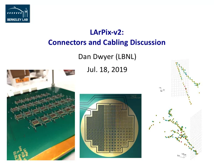
LArPix-v2: Cables and Connectors
Draft mechanical design for integration with 2x2 Demonstrator
(K. Skarpass)
2
Connector edge V2 Pixel Tile ArgonCube Module
LArPix-v2: Cables and Connectors
Rough needs for connectors/cables for 2x2 Demonstrator
Independent cable (bundle?) from each tile to flange à allow independent depowering of tile
4 cables per module corner, 16 cables per module
Proposed Cable budget (per tile):
N Ground 4 Power (VDDA x2, VDDD x2) 1 Analog Monitor 1 ADC Test 1 Reset-Sync 1 External Trigger 2 Clock/Anti-Clock 16 Data I/O (4 MOSI/MISO pairs) 26 + NGnd Total conductors à Suggests 32-pin connector?
Length: ~1 m minimum to ~2 m maximum, depending on tile vertical position in 2x2 module Thermal: 87 K to room temp Chemical: Compatible with high-purity LAr (doesn’t emit electronegative impurities) Other: Negligible (<200 e- ENC) cross-talk from Clock, Data I/O to analog side (VDDA, Analog Monitor) Three options for Clock and Data I/O signals:
Option A: ‘LArPix-v2-I/O’
Option B: ‘Mitch-I/O’
(see last week’s presentation) Option C: ‘Carl-I/O’ - Integrated low-power LVDS to/from ‘head node’ LArPix ASIC.
3
Net Voltage Other
VDDA +1.8 ~0.3 W/tile VDDD +0.8 to +1.8 ~0.3 W/tile Ana.Mon. 0 to VDDA
0 to VDDA
0 to VDDD CMOS, 5-10 MHz
0 to VDDD CMOS, 5-10 MHz CLK/~CLK 0 to VDDD See disc., 5-10 MHz Data I/O 0 to VDDD See disc., 5-10 MHz
LArPix-v2: Cables and Connectors
LArPix-v1 Approach:
Standard 0.1” two-row male header pin connectors 50-pin ribbon cable with 2x25 Female crimp connectors Advantages:
Disadvantages:
Some LArPix-v2 Options:
Option A: EXO approach (K. Skarpass)
Option B: ProtoDUNE approach
data twin-axial cable bundles
Option C: Other? Feedthrough: LArIAT-style
4
ProtoDUNE cables and connectors EXO cables and connectors
Twisted pair Twin-axial