
SLIDE 1
SALES PRESENTATION FOR
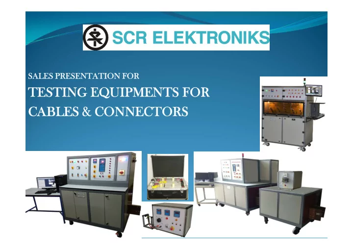
TESTING EQUIPMENTS FOR CABLES & CONNECTORS LIST OF TEST - - PowerPoint PPT Presentation
SALES PRESENTATION FOR TESTING EQUIPMENTS FOR CABLES & CONNECTORS LIST OF TEST EQUIPMENT PC BASED TEMPERATURE RISE TEST BENCH 10KA (25KA 5SEC) FOR CABLES AND CONNECTORS 1. PC BASED TEMPERATURE RISE TEST BENCH WITH 2000 A / 10.5 V CURRENT
SALES PRESENTATION FOR
1.
PC BASED TEMPERATURE RISE TEST BENCH 10KA (25KA 5SEC) FOR CABLES AND CONNECTORS
2.
PC BASED TEMPERATURE RISE TEST BENCH WITH 2000 A / 10.5 V CURRENT SOURCE
3.
HV INCLINED PLANE AND EROSION TESTER
4.
HOT WIRE IGNITION TESTER
5.
PC BASED TEST SETUP FOR 12 CORE CABLES
6.
TEST SETUP FOR FLEXIBLE PERFORMANCE OF WIRES & CABLES
What It Is?
junctions.
Current even as impedance of the cable changes due to rapid temperature rise), a specially designed step down transformer system, PC based control system, Temperature data logging
position of auto transformer (variac).
manual mode. CR/AL('K' type) type thermocouples are used for temperature sensing.
Models Available :
size of cable
additionally we can integrate the existing temperature measurement system at clients end, thus acting as an add on / retrofit solution
through switches.
logging.
mode.
range of cables and connectors
time current rating for cables
change is automatic and instantaneous without delay
PC BASED TEMPERATURE RISE TEST BENCH
What It Is?
junctions for tests upto 2000 A.
transformer system, PC based control system, Temperature data logging on PCand other indications . Digital voltmeter Primary Voltage indicates the position of auto transformer (variac).
manual mode. CR/AL('K' type) type thermocouples are used for temperature sensing.
Models Available :
maximum size of cable
additionally we can integrate the existing temperature measurement system at clients end, thus acting as an add on / retrofit solution
logging.
mode.
current cables and connectores
time current rating for cables
PC BASED TEMPERATURE RISE TEST BENCH
What It Is?
TESTER to carry out test specified in many standard to cover test method for the evaluation of the relative tracking and erosion resistance of insulating solid using liquid contaminant (ASTM D2303).
selection.
Models Available :
controlling an individual station, or a PC based wherein the PC controls all the stations simultaneously and independently of each other.
20 *4 LCD and membrane keypad for display of set test parameters and test status.
cables.
cables.
High Voltage Inclined Plane And Erosion Tester
What It Is?
1:2004 Annexure M.
high temperatures resulting from a component failure such as a conductor carrying far more than its rated current.
specimen when wrapped with an energized non-chrome resistive wire that dissipates a specified level of energy.
Models Available :
procured with the manual option (without PC)
must be considered in the selection and evaluation of a material for use in electrical equipment.
and manufacturers who use insulators in their products e.g. wiring accessories, appliances, etc.
wrapped around the specimen
Hot Wire Ignition Tester
What It Is?
Apparatus is tested by subjecting it to a Voltage much higher than the normal working
electrical stress punctures the insulation at its weakest spot foretelling a later calamity to unwary user.
Models Available :
Key Benefits :
for electrical equipment.
Features & Specifications :
What It Is?
and millivolt reading of the two. The user can compare the difference between the two cables.
Models Available :
briefcase.
Features & Specifications :
Key Benefits :
competitor.
TEST SETUP FOR FLEXIBLE PERFORMANCE OF WIRES & CABLES
Documentation That Will Be Provided With
Why SCR Elektroniks ?
Since 1975: Rich Experience In Test And Measurement Customized Solution Dedicated After Sales Support Team Designed More Than 100 Different Products In- House Team Of Micro-controller Design, Electrical And Electronic Design, Micro
Controller Development, Labview (PC) Software And PLC Logic, Production, Testing And Commissioning And Support
In-house Development Of Critical Electronic And Electrical Meters, Modules And
Components
ISO 9001 : 2015 Certified By Bureau Veritas – Maintaining High Quality In Our Internal
Process
Listed By IEC In The Past Fair And Consistent Pricing Our Ultimate Prize: Customer Delight
Sr. No Customer Name 1
Apar Cable
2
Garg Associates
3
Anand International
4
Raychem RPG Pvt Ltd