
SLIDE 1
SALES PRESENTATION FOR
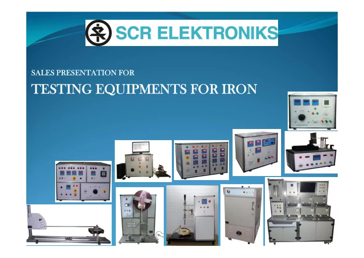
TESTING EQUIPMENTS FOR IRON LIST OF TEST EQUIPMENT Routine / Lab - - PowerPoint PPT Presentation
SALES PRESENTATION FOR TESTING EQUIPMENTS FOR IRON LIST OF TEST EQUIPMENT Routine / Lab Test: ENDURANCE TEST SETUP FOR THERMOSTAT OF IRON 1. ENDURANCE TEST SETUP FOR IRON 2. PC BASED ELECTRIC IRON TESTER 3. SAFETY TEST PANEL FOR IRON
SALES PRESENTATION FOR
Routine / Lab Test:
1.
ENDURANCE TEST SETUP FOR THERMOSTAT OF IRON
2.
ENDURANCE TEST SETUP FOR IRON
3.
PC BASED ELECTRIC IRON TESTER
4.
SAFETY TEST PANEL FOR IRON
5.
TEST SET UP TO CHECK TEMPERATURE DISTRIBUTION OF IRON
6.
DIGITAL TEMPERATURE INDICATOR & THERMOCOUPLE SENSOR
7.
VARIABLE VOLTAGE SOURCE
8.
EARTH CONTACT RESISTANCE TESTER
9.
GLOW WIRE TEST APPARATUS
10.
ENVIRONMENTAL TEST CHAMBER
11.
LABORATORY OVEN
Mechanical Test:
1.
APPARATUS FOR CHECKING STEAM EMISSION KNOB FOR 50000 CYCLES
2.
CORD GRIP TEST APPARATUS
3.
CORD GUARD FLEXING TEST PANEL
4.
IMPACT TEST APPARATUS IS 3854 1997 CLAUSE NO. 20 (FIG. 15)
5.
BALL PRESSURE TEST APPARATUS AS PER IS 8828
6.
DROP TEST APPARATUS
7.
SPRING HAMMER IMPACT TESTER
What It Is ?
which is used for carrying out endurance test for thermostat of iron for the required amount of time.
Models Available :
iron.
Basic Specifications :
displayed on Digital Display. One can set maximum no, of cycles (0 to 9999) or ON Time, after this the test will be terminated. In case the welding of contact i.e. It is on for long time without OFF condition or for contact i.e. No current for long time. The test will be terminated declaring Fail.
Salient Features :
a) Test ON b) Contact Open c) Contact Weld d) Test Over
Key Benefits :
during off time) and contact open (interrupted current during on time)
Key Photos :
Endurance Test Panel
What It Is ?
IRONS which is used for carrying out endurance & temperature measurement test of thermostat of iron.
6 stations.
Models Available :
stations for a different type of iron – Still, tests can be simultaneously conducted on different irons
Basic Specifications :
Salient Features :
Key Benefits :
Testing.
– adds to product consistency and brand value
Key Photos :
6 Station Endurance Test Panel
What It Is?
various tests mentioned in IS 366:1991 clauses 10,11,12,13 & 14 on the Iron under test.
1.
Heating Up Time Test
2.
Sole Plate Temperature Test
3.
Temperature Distribution Test
4.
Initial Over Swing/Excess Heating/Cyclic Fluctuation Test
Models Available :
Basic Specifications :
Salient Features :
sense the temperatures at different points of Iron under test.
tests on Iron easily.
Key Benefits :
accommodated.
temperature distribution test, sole plate temperature test, and Initial Over Swing/Excess Heating/Cyclic Fluctuation Test) for a domestic iron. Thus, it indirectly tests the bimetallic characteristics of the element inside the iron
Key Photos :
Pc Based Electric Iron Tester
What It Is ?
prescribed in IS302-1979. It is the most important and bought out item in the domestic iron routine testing
Insulation Test , Earth Leakage Current Test. The panel carries out different tests one by
Models Available :
earth bond current, and the rated current / wattage
Basic Specifications :
Salient Features :
Key Benefits :
Testing – But is mostly used in routine testing
Both in PC based and microcontroller based
connections, once plugged in, are automatic and contactor based
production factories
Key Photos :
Safety Test Panel For Iron
What It Is?
maintains the voltage with + / - 3 % of set value with Digital indication. Digital Temperature indicator having six channels for temperature measurement. Cr/Al type of thermocouple sensors are used for temperature sensing. Digital Meter used to indicate Voltage, Current, Wattage.
Models Available :
coated for superior finish. Three Terminals are brought out for output connections in front of the panel.
cover entire panel can be serviced easily during maintenance.
Basic Specifications :
Salient Features :
comments, etc.
Key Benefits :
various components which are key to this test bench
randomly pick a sample from the batch and compare its results
Key Photos :
Test Set Up To Check Temperature Distribution Of Iron
Digital Temperature Indicator:
CR/AL (K Type) Thermocouple Sensor:
Digital Temperature Indicator
What It Is?
test of Unit Under Test. It consists of Voltmeter, Ammeter, Wattmeter and Frequency meter for observing the values of different parameters.
equipment to be tested.
Features & Specifications:
Variable Voltage Source
What It Is?
say 25 A.
Models Available :
through the earthing circuit, but usually the tester is procured with 30 A capacity
Basic Specifications :
Resistance - 0.001 Resolution for 1.999 Ohms range) at 25 A current.
a) For mV – 0 to 200mV/2V range. b) For Resistance 0 to 1.999 Ohms.
a) Mains ON/OFF switch b) mV/Resistanace range switch Range.
Model.
current - thus assessing how well the product earth is 'bounded' to the system earthing
Earth Contact Resistance Tester
What It Is?
Models Available :
control on contact with the heating loop (most popular model – less costly than pc based version)
user management
Basic Specifications :
0.6 mm diameter pocket hole in temperature sheath resistant to 1000 degree centigrade
heating element touches the specimen.
with a shape as per the standard
mm.
mount the specimen
established
concluded
Precision scale is provided to measure the height of the flame
shifts from constant temperature mode to constant current mode once the loop touches the specimen)
takes place, the only force on the specimen stand (specimen) is that of a fixed weight
Automatic Glow Wire Tester
What It Is?
Temperature And Humidity Uniformity. This Is Achieved By Using One Set Of Motor & Blower In Baffle Wall Compartment To Push Treated Air In Working Chamber.
Transfer Inside The Chamber.
Helps To Mix Steam And Air Together And Pass Well Mixed Air Inside The Working Chamber.
Remains Equal.
Basic Specifications :
Movement.
Environmental Test Chamber
What It Is?
Laboratory Oven
SCR ELEKTRONIKS make following MECHANICAL TEST EQUIPMENTS for testing of IRON
with respect to various test standards such as BS, BIS, IEC, etc.
Although our core competence is electrical test equipment's our zest to deliver complete
testing solutions to our long term clients and so on has resulted us into designing state of an art mechanical apparatus such as :
knob.
displayed on 5 digit digital display.
rested on eccentric circular plate.
specification so that cord will not slip through the clamp. The testing specimen is passed through the hole provided on the hinged plate. The clamped or moulded portion of cable should rested on hinged plate.
the apparatus :
cable is clamped in such a way that , weights will lift upward, if the hinge plate lifts in upward direction.
are applied with out jerks.
Fabricated Cabinet is made to carryout both 90° & 180° flexing type.
a)
With 90° at 60 flexing's / min.
b) With 180° at 6 flexing's / min.
appliances for their mechanical strength.
the figure.
0.15 Kg.
pivoted at its upper end in such a way that it swings only in the vertical plane of the axis
2.0 N is applied to the face of the hammer to maintain the pendulum in horizontal
apparatus is so arranged that the pivot of the pendulum is vertically above the point of impact of the hammer. The striking element is then allowed to fall from such a height of 250 mm. Three such blows are applied to every part of the enclosure which is likely to be weak, including handle, levers and the like, but excluding single lamps and their covers if these do not protrude from the enclosure by more than 3 mm or have a surface not exceeding 3 cm (square).
Key Photos :
Cord Guard Test Apparatus Cord Grip Test Apparatus Impact Test Apparatus Apparatus for checking steam emission knob
What It Is?
respect to resistance to elevated operating temperature.
manufacturers and other electro-technical manufacturers who use insulating material in their electrical appliances. The BP21 is made of stainless steel for long life.
3854, IS 2215, BS, UL
Models Available :
test apparatus.
standards.
Basic Specifications :
hot environment
Ball Pressure Test Apparatus
What It Is ?
appliances for their mechanical strength.
dropped from a height of 40mm on to a rigidly supported steel plate having a thickness
not exceeding 20 drop/min.
standard, in particular with 8.1,15.2, and 29 is impaired. In case of doubt, supplementary insulation and reinforced insulation is subjected to the electric strength test of 16.3
enter the 1000 cycles in counter and press START push button to start the TEST. After 1000 cycles over Test Over buzzer will flash.
Drop Test Apparatus
What It Is?
domestic appliance / switchgear / wiring accessory under test against striking force derived from a mechanically charged spring hammer
Models Available :
Spring Impact Hammer
Documentation That Will Be Provided With
Why SCR Elektroniks ?
Since 1975: Rich Experience In Test And Measurement Customized Solution Dedicated After Sales Support Team Designed More Than 100 Different Products In- House Team Of Micro-controller Design, Electrical And Electronic Design, Micro
Controller Development, Labview (PC) Software And PLC Logic, Production, Testing And Commissioning And Support
In-house Development Of Critical Electronic And Electrical Meters, Modules And
Components
ISO 9001 : 2015 Certified By Bureau Veritas – Maintaining High Quality In Our Internal
Process
Listed By IEC In The Past Fair And Consistent Pricing Our Ultimate Prize: Customer Delight
Sr. No Customer Name 1
Bajaj
2
Havells
3
Elin Appliances
4
Maharaja Whiteline
5
Eveready