
SLIDE 1
SALES PRESENTATION ON
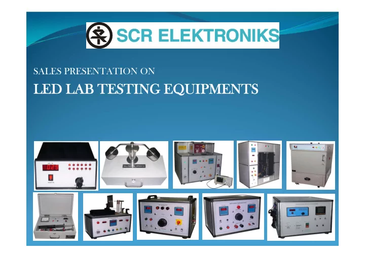
LED LAB TESTING EQUIPMENTS LIST OF TEST EQUIPMENT IMPULSE TESTER - - PowerPoint PPT Presentation
SALES PRESENTATION ON LED LAB TESTING EQUIPMENTS LIST OF TEST EQUIPMENT IMPULSE TESTER 1. GLOW WIRE TESTER 2. NEEDLE FLAME TEST APPARATUS 3. HIGH VOLTAGE TESTER 4. EARTH CONTACT RESISTANCE TESTER 5. DIGITAL TEMPERATURE INDICATOR AND
SALES PRESENTATION ON
1.
IMPULSE TESTER
2.
GLOW WIRE TESTER
3.
NEEDLE FLAME TEST APPARATUS
4.
HIGH VOLTAGE TESTER
5.
EARTH CONTACT RESISTANCE TESTER
6.
DIGITAL TEMPERATURE INDICATOR AND CR/AL TYPE (K TYPE) THERMOCOUPLE SENSOR
7.
TEMPERATURE RISE TEST PANEL
8.
BALL PRESSURE TEST APPARATUS
9.
TEST FINGURE APPARATUS
What It Is ?
duration as defined in IEC 61180. The product conforms to the following list of standards:
1.
Low Voltage Switchgear and Control gear: IS/IEC 60947 -2004 Cl. No: 8.3.3.4.1
2.
Circuit Breakers: IS/IEC 60898:2002 Cl.no.: 9.7.6.1 & 97.6.2
3.
Residual Current Operated breakers: IEC 61008 & 61009 : Cl.no.: 9.20
4.
In addition, the test (commonly known as 1.2 / 50 uS test) is referred in a variety different standards.
Models Available :
front panel.
PLC module. Results are displayed on LCD display. Output is provided on oscilloscope
unique advantage over contactor: It prevents the bouncing of contactor contacts generating a relatively accurate wave-shape of a very short duration.
depending on the model chosen (Linear Scale)
contactor.
What It Is?
Models Available :
control on contact with the heating loop (most popular model – less costly than pc based version)
user management
Basic Specifications :
0.6 mm diameter pocket hole in temperature sheath resistant to 1000 degree centigrade
heating element touches the specimen.
with a shape as per the standard
mm.
mount the specimen
established
concluded
Precision scale is provided to measure the height of the flame
shifts from constant temperature mode to constant current mode once the loop touches the specimen)
takes place, the only force on the specimen stand (specimen) is that of a fixed weight
Automatic Glow Wire Tester
What It Is?
testing.
directly conducting parts & also parts of insulators.
Models Available :
0.5.
s.
Needle Flame Test Apparatus
What It Is?
flowing across the Earth Terminal.
Basic Specifications :
b) Shrouded type Push Button for H.T. ON. c) H.V. Transformer heavy duty epoxy cast.
a) High Voltage and leakage current on separate meters. b) Separate lamp indication for H.T. ON, OK, NOT OK
What It Is?
say 25 A.
Models Available :
through the earthing circuit, but usually the tester is procured with 30 A capacity
Basic Specifications :
Resistance - 0.001 Resolution for 1.999 Ohms range) at 25 A current.
a) For mV – 0 to 200mV/2V range. b) For Resistance 0 to 1.999 Ohms.
a) Mains ON/OFF switch b) mV/Resistanace range switch Range.
Model.
current - thus assessing how well the product earth is 'bounded' to the system earthing
Earth Contact Resistance Tester
Digital Temperature Indicator:
CR/AL (K Type) Thermocouple Sensor:
Digital Temperature Indicator
What It Is?
% of set value with Digital indication, Digital Temperature indicator having twelve channels for temperature measurement.
voltmeter used to indicate position of autotransformer.
is Table Top Mounting Type.
Basic Specifications :
Auto mode and with switch in manual mode.
Luminaire.
switch selectable.
TEMPERATURE RISE TEST PANEL
What It Is?
respect to resistance to elevated operating temperature.
manufacturers and other electro-technical manufacturers who use insulating material in their electrical appliances. The BP21 is made of stainless steel for long life.
3854, IS 2215, BS, UL
Models Available :
test apparatus.
standards.
Basic Specifications :
hot environment
Ball Pressure Test Apparatus
What It Is?
shutters, when the plug is in partial with the product.
a live Finger.
the Test Product.
Models Available :
Basic Specifications :
appliances against electric shock during human handling – thus the use is universal
Test Finger Apparatus
What It Is?
Temperature And Humidity Uniformity. This Is Achieved By Using One Set Of Motor & Blower In Baffle Wall Compartment To Push Treated Air In Working Chamber.
Transfer Inside The Chamber.
Helps To Mix Steam And Air Together And Pass Well Mixed Air Inside The Working Chamber.
Remains Equal.
Basic Specifications :
Movement.
Environmental Test Chamber
What It Is?
Laboratory Oven
Why SCR Elektroniks ?
Since 1975: Rich Experience In Test And Measurement Customized Solution Dedicated After Sales Support Team Designed More Than 100 Different Products In- House Team Of Micro-controller Design, Electrical And Electronic Design, Micro
Controller Development, Labview (PC) Software And PLC Logic, Production, Testing And Commissioning And Support
In-house Development Of Critical Electronic And Electrical Meters, Modules And
Components
ISO 9001 : 2015 Certified By Bureau Veritas – Maintaining High Quality In Our Internal
Process
Listed By IEC In The Past Fair And Consistent Pricing Our Ultimate Prize: Customer Delight
Sr.
No.
Customer
1 Philips Electronics India Pvt. Ltd, Noida 2 Esko Die Casting Pvt. Ltd., Faridabad 3 Jhunkam Lighting Systems Pvt. Ltd., Daman 4 Ray-hans Technologies Pvt. Ltd., Mysore 5 Uma Luminaires Pvt. Ltd., Nagpur 6 SFO Technologies Pvt. Ltd., Bangalore 7 Uma Poly Solution Pvt. Ltd., Howrah 8 Elin Electronics Ltd., Ghaziabad 9 Maraica Industries, Howrah 10 Surya Roshni Ltd., New Delhi, M.P.
11 Havells India Ltd, Rajasthan, Noida 12 Starline Industries India Pvt. Ltd., Coimbatore 13
14 Rama Industries, Vasai 15 Tech Electro Com, Ahmedabad 16 Arraystorm Lighting Pvt. Ltd., Bangalore 17 Inled Loghting LLP, Pune 18 Konark Product HP Capital Warehouse, HP 19 Max Light and Luminiers Pvt. Ltd., Bhiwandi 20 Glo Lighting Industries, Kolkata 21 Samudra Electronics System Pvt. Ltd, Pune 22
23 Varun Pressings PVT. LTD., Pune 24 META Switchgear Co, Saudi Arabia 25 C & S Electric LTD, Noida