
SLIDE 1
Inverse Kinematics
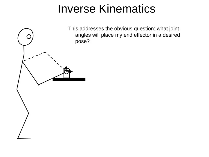
This addresses the obvious question: what joint angles will place my end effector in a desired pose?
Inverse Kinematics This addresses the obvious question: what joint - - PowerPoint PPT Presentation
Inverse Kinematics This addresses the obvious question: what joint angles will place my end effector in a desired pose? Inverse kinematics Closed form (analytical) solution: a sequence or set of equations that can be solved for the desired
This addresses the obvious question: what joint angles will place my end effector in a desired pose?
Closed form (analytical) solution: a sequence or set of equations that can be solved for the desired joint angles
not collide with the body. Iterative (numerical) solution: numerical iteration toward a desired goal position (variation on Newton’s method)
There is no general analytical inverse kinematics solution
1
2
3
4
5
6
Spherical wrist: the axes of the last three joints intersect in a point. Consider this 6-joint robot:
1
q
2
q
3
q
4
q
5
q
6
q
Problem:
eff eff eff
( )
n
4 3 2 1
Note:
be represented by six numbers)
redundant solutions.
component (the first three joints) and an orientation component (the last three joints)
Since it’s a spherical wrist, the last three joints can be thought of as rotating about a point.
effector (sometimes this is called the “tool” transform):
1
q
2
q
3
q
4
q
5
q
6
q
Solution:
wrist:
eff swT 1 −
eff sw eff b sw b
First, solve for . (look down from above)
1
q
2
q
3
q
4
q
5
q
6
q
g g y
1 = 1
Goal position in horizontal plane
1
g g y
1
Next, solve for . (look at the manipulator orthogonal to the plane of the first two links)
1
q
2
q
3
q
4
q
5
q
6
q
( )
g g c
2 1 2 2 2 1 2 2
3
2
3
1
2
2 2 2 c
2 2 2 g g g
where
c
and is the height of the first link
( )
2 3
Next, solve for . (continue to look at the manipulator
first two links)
1
q
2
q
3
q
4
q
5
q
6
q
2
2
3
1
2
( )
2 2
g g g
( )
3 2 1 3 2
2
Finally, the last three joints completely specify the
Euler angles
just calculate the ZYZ Euler angles corresponding to the desired orientation.
1
q
2
q
3
q
4
q
5
q
6
q
( )
zyz
θ ψ θ ψ θ θ φ ψ φ ψ θ φ ψ φ ψ θ φ θ φ ψ φ ψ θ φ ψ φ ψ θ φ
33 2 33 ,
13 23,
31 32,
You can do similar types of things for a humanoid (7-DOF) arm.
manifold of solutions… elbow Spherical wrist Spherical shoulder General strategy:
(note that you have to choose an elbow orbit angle)