Internetworking Outline Best Effort Service Model Global - - PDF document

internetworking
SMART_READER_LITE
LIVE PREVIEW

Internetworking Outline Best Effort Service Model Global - - PDF document

Internetworking Outline Best Effort Service Model Global Addressing Scheme 1 Internetworking Concatenation of Different Networks Network 1 (Ethernet) H7 R3 H8 H1 H2 H3 Network 4 (point-to-point) Network 2 (Ethernet) R1 R2 H4


slide-1
SLIDE 1

1

1

Internetworking

Outline

Best Effort Service Model Global Addressing Scheme

2

Internetworking

  • Concatenation of Different Networks

R2 R1 H4 H5 H3 H2 H1 Network 2 (Ethernet) Network 1 (Ethernet) H6 Network 4 (point-to-point) H7 R3 H8 Network 3 (FDDI)

slide-2
SLIDE 2

2

3

IP Internet

  • Connecting Problem 1: Heterogeneity of Networks

– Solution: Layered Protocol Stack (IP over …… )

  • Problem 2: Scalability in Routing and Addressing

– Solution: Address Hierarchy

R1 R2 R3 H1 H8 ETH FDDI IP ETH TCP FDDI PPP PPP ETH IP ETH TCP IP IP IP 4

Service Model

  • Connectionless (datagram-based)
  • Best-effort delivery (unreliable service)

– packets can be lost, delayed, duplicated, delivered out of order.

  • Datagram format: IP header

Version HLen TOS Length Ident Flags Offset TTL Protocol Checksum SourceAddr DestinationAddr Options (variable) Pad (variable) 4 8 16 19 31 Data

slide-3
SLIDE 3

3

5

IP Header

  • Version (always set to the value 4 for IP v4)
  • IP Header Length (number of 32 -bit words forming the header,

usually five)

  • Size of Datagram (in bytes, header + data)
  • Flags 3 bits: R (reserved bit set to 0) DF (Don't fragment ) MF (More

fragments)

  • Time To Live (Number of hops /links which the packet may be routed
  • ver, decremented by most routers - used to prevent accidental routing

loops)

  • Protocol (the type of transport packet being carried (e.g. 1 = ICMP; 6 =

TCP; 17= UDP).

  • Header Checksum (A 1's complement checksum of IP header, updated

whenever the packet header is modified by a node. Packets with an invalid checksum are discarded by all nodes in an IP network)

  • Source Address / Destination Address

6

Fragmentation and Reassembly

  • Each network has some MTU (max trans. Unit)
  • Design decisions

– fragment (re-fragment) when necessary (MTU < Datagram) – fragments are self-contained datagrams – delay reassembly until destination host – do not recover from lost fragments – try to avoid fragmentation at senders (packet size < local MTU)

H1 R1 R2 R3 H8 ETH FDDI PPP IP (376) PPP IP (512) PPP IP (512) (512) ETH IP ETH IP (512) ETH IP (376) IP (1400) IP (1400) R1 R2 R3

slide-4
SLIDE 4

4

7

Example

(a) Ident = x Start of header Rest of header 1400 data bytes Offset = 0 (b) Ident = x Start of header Rest of header 512 data bytes Offset = 0 1 Ident = x Rest of header 512 data bytes Offset = 64 1 Start of header Ident = x Start of header Rest of header 376 data bytes Offset = 128

  • FDDI MTU 523 bytes = 20 + 512
  • Fragmentation Offset offset from the start
  • f the original sent packet, in units of 8

bytes (512 / 8 = 64)

  • Identification ( 16-bit number which

together with the source address uniquely identifies this packet)

  • Flag MF (more fragments) = 1;

8

Global Addresses

  • Properties

– globally unique – hierarchical: network + host – Class A, B, C

  • Dot Notation

– 10.3.2.4 – 128.96.33.81 – 192.12.69.77

Network Host 7 24 (a) Network Host 14 16 1 (b) Network Host 21 8 1 1 (c)

slide-5
SLIDE 5

5

9

  • Every datagram contains destination’s address
  • if connected to destination network, then forward to

the host in LAN

– If network number of destination IP == my network number

  • if not directly connected, then forward to some router

– each host has a default router configured

  • Each router maintains a forwarding table

– forwarding table maps network number (rather than host address) into next hop or interface number (if directly connected) – Otherwise send to its (the router’s) default router

Datagram Forwarding Strategy

10

Traffic: H1 → H3, H1 → H8 R1: default router is R2 R2 Routing Table: Network Number Next Hop Interface 1 R3 interface 1 2 R1 interface 0 3

  • interface 1

4

  • interface 0

R2 R1 H4 H5 H3 H2 H1 Network 2 (Ethernet) Network 1 (Ethernet) H6 Network 4 (point-to-point) H7 R3 H8 Network 3 (FDDI)

slide-6
SLIDE 6

6

11

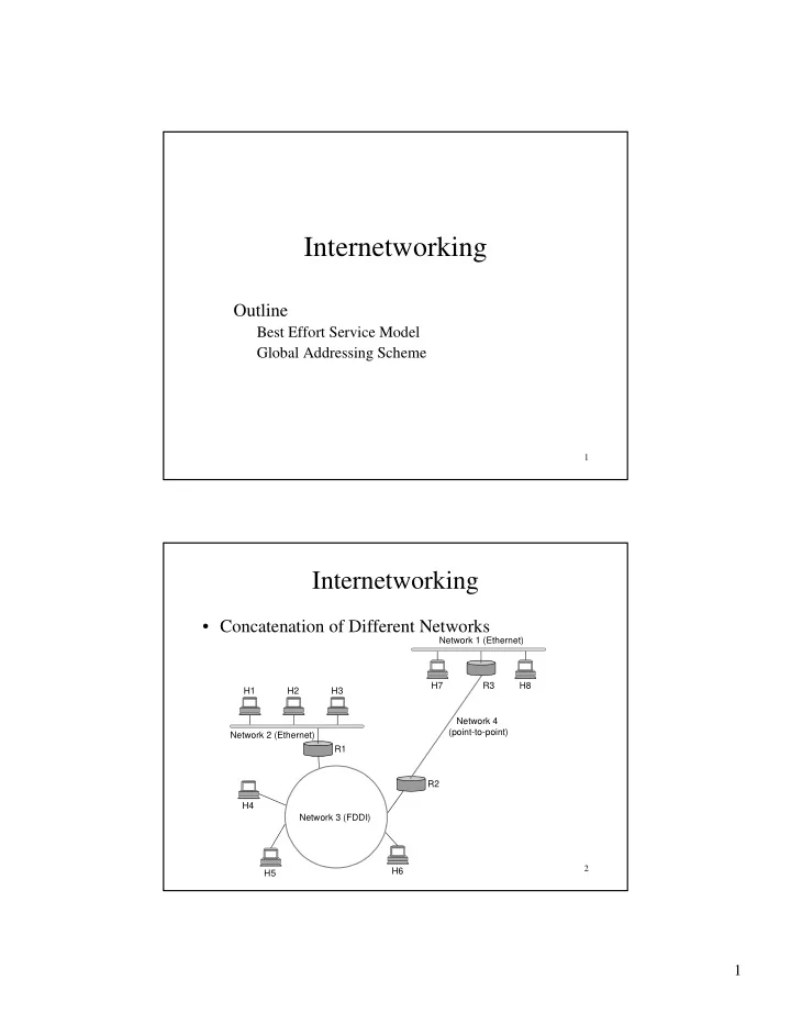
Address Translation in LAN

  • Map IP addresses into physical addresses of the destination

host (if connected directly) or the next hop router

  • ARP

– Each host caches its table of IP to physical address bindings – table entries are discarded if not refreshed

  • timeout in about 10 minutes

– broadcast request if IP address not in table – target machine send its physical address to the sender – target machine also updates add entry of the source in its table

  • It is likely that the target will send IP packets to the source later on.

– Other hosts (who receives the broadcasted request) update table if already have an entry

12

ARP Details

  • Request Format

– HardwareType: type of physical network (e.g., Ethernet) – ProtocolType: type of higher layer protocol (e.g., IP) – HLEN & PLEN: length of physical and protocol addresses – Operation: request=1 or response=2

TargetHardwareAddr (bytes 2 5) TargetProtocolAddr (bytes 0 3) SourceProtocolAddr (bytes 2 3) Hardware type = 1 ProtocolType = 0x0800 (IP) SourceHardwareAddr (bytes 4 5) TargetHardwareAddr (bytes 0 1) SourceProtocolAddr (bytes 0 1) HLen=48(Eth) PLen=32(IP) Operation SourceHardwareAddr (bytes 0 ―3) 8 16 31 ― ― ― ― ― ―

slide-7
SLIDE 7

7

13

Internet Control Message Protocol (ICMP)

  • Error/control messages sent by routers to the source IP.
  • Echo (ping)
  • TTL exceeded (traceroute)
  • Redirect

– E.g. Two routers are attached to the network. – Can be returned by the default router of the host

  • Destination Unreachable / Fragmentation Needed and DF Set

– On some modern computers, Don't Fragment (DF) flag is set in the IP header. – The router with smaller MTU discards the IP datagram and sends an ICMP message (type 3 / subtype 4) with its MTU to the sending host. – PMTU (Path MTU) discovery (RFC 1191) – Non-PMTU-compliant routers or firewalls may cause problem.