
SLIDE 1
Fire and Gas Mapping. Optimized.
Developed by Insight Numerics www.insightnumerics.com
Slide 1
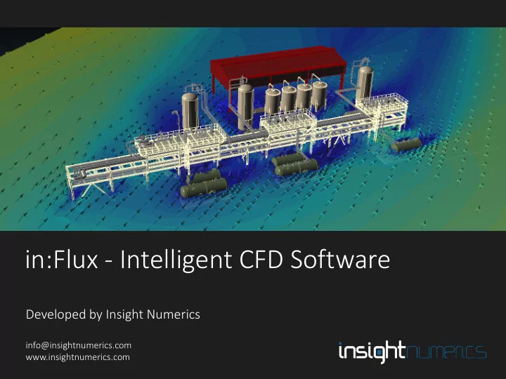
in:Flux - Intelligent CFD Software
Developed by Insight Numerics
info@insightnumerics.com www.insightnumerics.com
in:Flux - Intelligent CFD Software Developed by Insight Numerics - - PowerPoint PPT Presentation
in:Flux - Intelligent CFD Software Developed by Insight Numerics Slide 1 info@insightnumerics.com Developed by Insight Numerics www.insightnumerics.com Fire and Gas Mapping. Optimized. www.insightnumerics.com Introduction to in:Flux in:Flux
Fire and Gas Mapping. Optimized.
Developed by Insight Numerics www.insightnumerics.com
Slide 1
Developed by Insight Numerics
info@insightnumerics.com www.insightnumerics.com
Developed by Insight Numerics www.insightnumerics.com
Slide 2
Developed by Insight Numerics www.insightnumerics.com
Slide 3
boundary conditions, numerical setup and post-processing.
simulations take 2-10 minutes, while dispersion simulations are typically 10-30 minutes.
run in a single day.
management easy. No CFD expertise is required – the automatic setup ensures very high quality CFD simulations.
Developed by Insight Numerics www.insightnumerics.com
Slide 4
defined simply by choosing a wind direction and wind speed.
Developed by Insight Numerics www.insightnumerics.com
Slide 5
grading from the ground to capture the high gradients.
Developed by Insight Numerics www.insightnumerics.com
Slide 6
Developed by Insight Numerics www.insightnumerics.com
Slide 7
regions of high gradient. The mesh size for ventilation is 0.5 meters.
Developed by Insight Numerics www.insightnumerics.com
Slide 8
available, including contours:
Developed by Insight Numerics www.insightnumerics.com
Slide 9
Developed by Insight Numerics www.insightnumerics.com
Slide 10
Developed by Insight Numerics www.insightnumerics.com
Slide 11
an upstream pressure, temperature and composition. Alternatively, emission sources such as exhaust plumes can be set.
database.
Developed by Insight Numerics www.insightnumerics.com
Slide 12
and a wind simulation. No further setup is required.
Developed by Insight Numerics www.insightnumerics.com
Slide 13
concentration gradient. The mesh can be set to automatically expand to include certain concentrations. Minimum mesh size is 0.1 times the diameter of the leak.
Developed by Insight Numerics www.insightnumerics.com
Slide 14
dispersed gas clouds. These can be set up as concentrations of %volume, ppm, %LEL and %UEL.
Developed by Insight Numerics www.insightnumerics.com
Slide 15
regions can be used to calculate cloud volumes. All data is exportable to
Developed by Insight Numerics www.insightnumerics.com
Slide 16
scheduler, shown below.
Developed by Insight Numerics www.insightnumerics.com
Slide 17
Developed by Insight Numerics www.insightnumerics.com
Slide 18
validation test cases will be provided with the software, and the users can verify the results from these cases and re-run them if needed.
as well as other CFD software such as Ansys-CFX, FLUENT and OpenFOAM.
validation report will be published on the commercial release date.
assumptions used by FLACS are accurate (e.g. geometry being represented as axis-aligned boxes and cylinders, porous regions etc.). If FLACS gives inaccurate results due to these underlying assumptions, in:Flux will not give the same results, as in:Flux uses the full geometry model without using any porous regions.
Developed by Insight Numerics www.insightnumerics.com
Slide 19