
SLIDE 1
definition • design • development
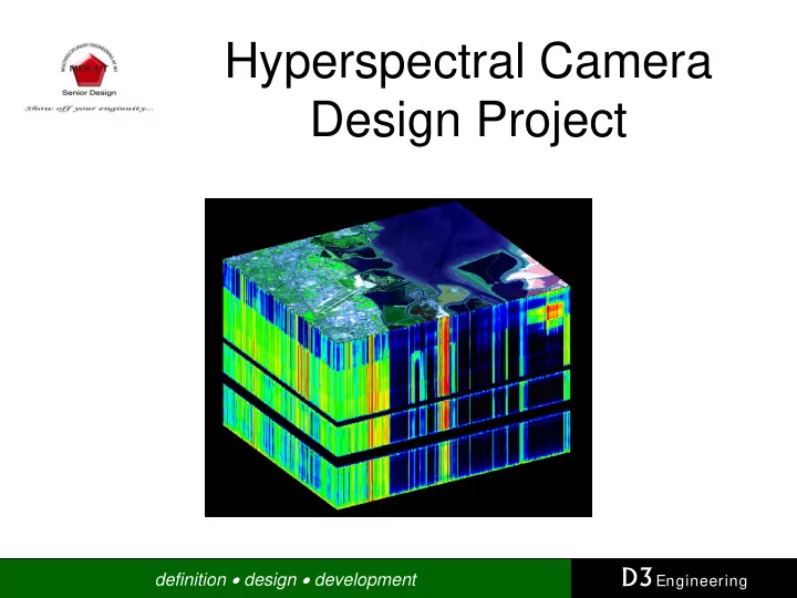
Hyperspectral Camera Design Project D3 Engineering definition - - PowerPoint PPT Presentation
Hyperspectral Camera Design Project D3 Engineering definition design development Team Members Will Shaffer Electrical Engineering Sponsored by: Jeff Sidoni D3 Engineering Electrical Engineering 222 Andrews Street
definition • design • development
definition • design • development
– Electrical Engineering
– Electrical Engineering
– Mechanical Engineering
– Mechanical Engineering
definition • design • development
definition • design • development
reflected energy to incident energy as a function of wavelength
spectral signature that is used for identification after a data set is acquired.
5 10 15
10 20 30 40 50 60 70 Wavelength λ (μm) % Reflectance Asphalt Dry Grass Granite Grass Dark Soil
definition • design • development
definition • design • development
in a target to be acquired.
target.
plane or satellite.
definition • design • development
in a single frame.
data sets can be captured without the need of a scanning mirror.
definition • design • development
nature, are very large
hundred bands of the spectrum.
two of the axes are spatial and one is spectral.
definition • design • development
definition • design • development
– Military
– Agricultural
– Mineral Exploration – Environmental Research
– Medical
– Food Industry
illness prevention
– Counterfeit Currency
definition • design • development
even multispectral imaging systems.
definition • design • development
definition • design • development
– Uses a single CMOS or CCD imager – Captures spectra from ~400 to ~850nm (Visible Light) – Has spectral resolution of 25-50nm – Develop back end software to acquire and process a hyperspectral data set and extract basic information such as material identification – Utilizes hardware already developed and tested by D3 Engineering for the image acquisition and motor control for the scanning mirror
definition • design • development
Processing Board Motion Board Imager Board
Image Sensor DSP
Video Data USB Communication I2C Serial Communications
Motion Control SDRAM FLASH
5VDC
M i r r
Target
definition • design • development
ID Task Name Duration Start Finish 1 Hyperspectral Camera Design 124 days Mon 12/5/05 Thu 5/25/06 2 Requirements Generation 2 w ks Mon 12/5/05 Fri 12/16/05 3 Design Documentation 2 w ks Mon 12/19/05 Fri 12/30/05 4 Initial Prototyping w / CDK 2 w ks Mon 12/19/05 Fri 12/30/05 5 Working Camera 2 w ks Mon 1/2/06 Fri 1/13/06 6 Preliminary Design R eview 1 day Fri 2/24/06 Fri 2/24/06 7 CDK 61 days Mon 1/2/06 Mon 3/27/06 8 Camera Softw are D evelopment 9.2 w ks Mon 1/2/06 Mon 3/6/06 9 1Mpixel 1 w k Tue 3/7/06 Mon 3/13/06 10 Frequency registration 2 w ks Tue 3/14/06 Mon 3/27/06 11 Optical Subsystem 40 days Mon 2/27/06 Fri 4/21/06 12 Use Spectrograph Optics 7 w ks Mon 2/27/06 Fri 4/14/06 13 Optical Design 2 w ks Mon 2/27/06 Fri 3/10/06 14 Lightpath Diagram 2 w ks Mon 3/13/06 Fri 3/24/06 15 Simulation 2 w ks Mon 3/27/06 Fri 4/7/06 16 Testing 2 w ks Mon 4/10/06 Fri 4/21/06 17 Scanning Mirror 20 days Mon 2/27/06 Fri 3/24/06 18 Linear stepper motor 4 w ks Mon 2/27/06 Fri 3/24/06 19 Mechanical Structure 4 w ks Mon 2/27/06 Fri 3/24/06 20 Software 45 days Mon 2/27/06 Fri 4/28/06 21 Raw Data Dow nlaod 1 w k Mon 2/27/06 Fri 3/3/06 22 Conversion to Matlab 2 w ks Mon 3/6/06 Fri 3/17/06 23 Frequency Resolution 3 w ks Mon 3/20/06 Fri 4/7/06 24 Create data Cube 3 w ks Mon 4/10/06 Fri 4/28/06 25 Mechanical 50 days Mon 2/27/06 Fri 5/5/06 26 Mirror 2 w ks Mon 2/27/06 Fri 3/10/06 27 Enclosure 4 w ks Mon 3/13/06 Fri 4/7/06 28 Optical Mounts 4 w ks Mon 4/10/06 Fri 5/5/06 29 Intergration 20 days Mon 4/24/06 Fri 5/19/06 30 Testing 3 w ks Mon 4/24/06 Fri 5/12/06 31 Verify vs Requirements 1 w k Mon 5/15/06 Fri 5/19/06 32 Final Report 1 w k Fri 5/19/06 Thu 5/25/06 1/2 4 11 18 25 1 8 15 22 29 5 12 19 26 5 12 19 26 2 9 16 23 30 7 14 21 28 4 11 Dec '05 Jan '06 Feb '06 Mar '06 Apr '06 May '06 Jun '06
definition • design • development
– Optics System
– Image System / Algorithm Development
– Scanning Mirror Motor Control
– Mechanical Components
definition • design • development
definition • design • development
definition • design • development
definition • design • development
definition • design • development
TARGE T
MIRROR ENCLOSUR E BAFFLE PRISM LENS (3) PLACE S
definition • design • development
TARGE T MIRROR ENCLOSUR E BAFFLE PRIS M LENS (3) PLACES
definition • design • development
camera’s, Specim, a company in Finland was brought to attention by Scott Reardon
(PGP) was discussed
hyperspectral imaging and his invention of the PGP
definition • design • development
definition • design • development
lamda vs. h
10 20 30 . 4 . 4 5 . 5 . 5 5 . 6 . 6 5 . 7 . 7 5 . 8 . 8 5 . 9 . 9 5 1 1 . 5 lamda (nm) h (mm) Series1
definition • design • development
Wavelength vs. Optimized Refracted Angle
0.01 0.02 0.03 0.4 0.45 0.5 0.55 0.6 0.65 0.7 0.75 0.8 0.85 0.9 0.95 1 1.05 Lamda (nm) Theta_t2-theta_not (deg) Series1
definition • design • development
Detector size Vs Input angle
10 20 30 40 50 60 70 80 90 100 10 20 30 40 50 60 70 Incident Angle (deg) Focal Plane Size (mm) Series1
definition • design • development
detector size vs. prism angle
5 10 15 20 25 30 35 40 45 50 10 20 30 40 50 60 70 80 prism angle (deg) detector size (mm) Series1 Series2 Series3 Series4 Series5 Series6 Series7 Series8 Series9 Series10 Series11 Series12 Series13 Series14 Series15
definition • design • development
monochromator
definition • design • development
definition • design • development
definition • design • development
definition • design • development
definition • design • development
definition • design • development
definition • design • development
Edmund Optics handheld spectrograph.
lamp.
the spectrum.
definition • design • development
definition • design • development
Prism 1 LPF Covering glass Grating SPF Prism 2 Substrate glass
definition • design • development
element in the ImSpector.
definition • design • development
definition • design • development
definition • design • development
definition • design • development
definition • design • development
– Ease development of algorithms for normalization and classification – Eventually move final processing inside the DSP
definition • design • development
– CMOS vs. CCD
depth
implement a CCD sensor
– Texas Instruments DSP
definition • design • development
Processing Board Imager Board
1.3 MegaPixel 10 Bit CMOS Imager DSP C6416
Video Data USB I2C Serial Communications
SDRAM FLASH
5VDC
Imager0 Optics
definition • design • development
– Camera calibration – Reflectance conversion – Image normalization – Spectral Mixing Correction – Material Classification against reference libraries
definition • design • development
Stages of Development:
baseline for data acquisition
angular velocity to accommodate imager
rotor position feedback
external velocity control
definition • design • development
100 10k 100 10k 10k 100 10k 100 47k 47k 1k 1k .033 .033 IRFZ44E IRFZ44E IRFZ44E IRFZ44E 1uF IN 2 SHDN 3 LO 5 HO 7 COM 4 VB 8 VCC 1 VS 6 IR2104 PWM_A1+ 820nF ZMM5251B 100 uF 1uF
Vdd Vdd
3 1 2
MtrDA1- MtrDA1+ 820nF
Vmm
IN 2 SHDN 3 LO 5 HO 7 COM 4 VB 8 VCC 1 VS 6 IR2104
V3_3/2 ViA1
Motor Current Sense Half - Bridge Driver Half - Bridge Driver
PWM_A1-
definition • design • development
frequency
comparison with the percentage values stored in a table
down the transition through the look-up table
definition • design • development
Effective Driver Signal
definition • design • development
for optimized data acquisition
definition • design • development
tan(20 ) y d = ⋅ °
Target Width 2y =
1
tan( ) y d Δ = ⋅ ΔΘ
2 1
tan(2 ) y d y Δ = ⋅ ΔΘ − Δ
3 2 1
tan(3 ) y d y y Δ = ⋅ ΔΘ − Δ − Δ
( )
1 1
tan( ) 1
i i j j
y d i y i
− =
Δ = ⋅ ΔΘ − Δ ∀ >
( )
( )
1 2 2 1 1 1
tan( ) tan( ) tan ( 1)
i i i i j j j j j j
y d i y d i d i y y
− − − = = =
⎛ ⎞ Δ = ⋅ ΔΘ − Δ = ⋅ ΔΘ − − ΔΘ − Δ − Δ ⎜ ⎟ ⎝ ⎠
( ) ( )
tan tan ( 1)
i
y d i d i Δ = ⋅ ΔΘ − ⋅ − ΔΘ
definition • design • development
d [m] y [m] μStep Size Δθ # Slits/ Half Image
[mm] Min Δy [mm] Max Δy [mm] 0.0625 0.225 88 4.136 3.927 4.430 0.03125 0.1125 177 2.056 1.963 2.220 0.015625 0.05625 355 1.025 0.982 1.111 0.0078125 0.028125 711 0.512 0.491 0.556 0.00390625 0.0140625 1422 0.256 0.245 0.278 0.0625 0.225 88 8.272 7.854 8.860 0.03125 0.1125 177 4.113 3.927 4.439 0.015625 0.05625 355 2.051 1.963 2.222 0.0078125 0.028125 711 1.024 0.982 1.112 0.00390625 0.0140625 1422 0.512 0.491 0.556 0.0625 0.225 88 12.408 11.781 13.289 0.03125 0.1125 177 6.169 5.890 6.659 0.015625 0.05625 355 3.076 2.945 3.333 0.0078125 0.028125 711 1.536 1.473 1.667 0.00390625 0.0140625 1422 0.768 0.736 0.834 0.0625 0.225 88 16.544 15.708 17.719 0.03125 0.1125 177 8.225 7.854 8.878 0.015625 0.05625 355 4.101 3.927 4.444 0.0078125 0.028125 711 2.048 1.963 2.223 0.00390625 0.0140625 1422 1.024 0.982 1.112 0.0625 0.225 88 20.680 19.635 22.149 0.03125 0.1125 177 10.282 9.817 11.098 0.015625 0.05625 355 5.126 4.909 5.555 0.0078125 0.028125 711 2.560 2.454 2.779 0.00390625 0.0140625 1422 1.280 1.227 1.390 1.092 5 1.820 4 1.456 3 3.6 ° per Full Step: 0.364 1 2 0.728
Comparison of Open-Loop Control Variables
definition • design • development
without the use of an encoder
produce voltage signals proportional to the rotor’s displacement angle
definition • design • development
d [m] y [m] μSteps / Full Rev. Δθ # Slits/ Half Image
Max Δy [mm] 40000 0.00900 2222 0.163802986 0.1570796 0.1778740 45000 0.00800 2500 0.145588094 0.1396263 0.1581152 50000 0.00720 2777 0.131065983 0.1256637 0.1422943 55000 0.00655 3055 0.119139193 0.1142397 0.1293622 60000 0.00600 3333 0.109201990 0.1047198 0.1185849 40000 0.00900 2222 0.327605971 0.3141593 0.3557479 45000 0.00800 2500 0.291176187 0.2792527 0.3162304 50000 0.00720 2777 0.262131966 0.2513274 0.2845886 55000 0.00655 3055 0.238278386 0.2284795 0.2587244 60000 0.00600 3333 0.218403981 0.2094395 0.2371698 40000 0.00900 2222 0.491408957 0.4712389 0.5336219 45000 0.00800 2500 0.436764281 0.4188790 0.4743456 50000 0.00720 2777 0.393197948 0.3769911 0.4268829 55000 0.00655 3055 0.357417579 0.3427192 0.3880866 60000 0.00600 3333 0.327605971 0.3141593 0.3557547 40000 0.00900 2222 0.655211943 0.6283185 0.7114959 45000 0.00800 2500 0.582352375 0.5585054 0.6324608 50000 0.00720 2777 0.524263931 0.5026548 0.5691772 55000 0.00655 3055 0.476556772 0.4569589 0.5174488 60000 0.00600 3333 0.436807962 0.4188790 0.4743396 40000 0.00900 2222 0.819014929 0.7853982 0.8893698 45000 0.00800 2500 0.727940469 0.6981317 0.7905761 50000 0.00720 2777 0.655329914 0.6283185 0.7114715 55000 0.00655 3055 0.595695964 0.5711987 0.6468111 60000 0.00600 3333 0.546009952 0.5235988 0.5929245 Kruse Control 1 0.364 2 0.728 5 1.820 3 1.092 4 1.456
Slit Width Analysis for Kruse Controlled System
definition • design • development
– Project enclosure – Scanning mirror fixture – Optical mounts
definition • design • development
definition • design • development
definition • design • development
definition • design • development