SLIDE 1
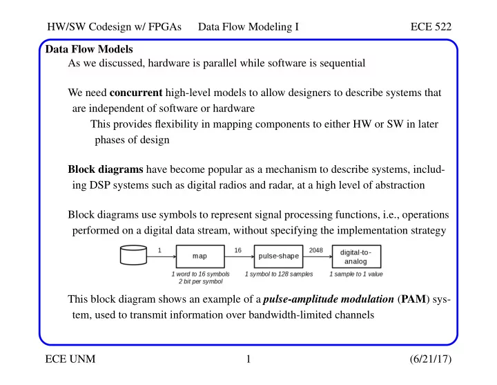
HW/SW Codesign w/ FPGAs Data Flow Modeling I ECE 522 ECE UNM 1 (6/21/17) Data Flow Models As we discussed, hardware is parallel while software is sequential We need concurrent high-level models to allow designers to describe systems that are independent of software or hardware This provides flexibility in mapping components to either HW or SW in later phases of design Block diagrams have become popular as a mechanism to describe systems, includ- ing DSP systems such as digital radios and radar, at a high level of abstraction Block diagrams use symbols to represent signal processing functions, i.e., operations performed on a digital data stream, without specifying the implementation strategy This block diagram shows an example of a pulse-amplitude modulation (PAM) sys- tem, used to transmit information over bandwidth-limited channels
SLIDE 2
HW/SW Codesign w/ FPGAs Data Flow Modeling I ECE 522 ECE UNM 2 (6/21/17) Data Flow Models The PAM system reads a file of binary data in 32-bit chunks The map function converts the 32-bits of each word to 16 2-bit symbols (PAM-4 is used to refer to such systems Each 2-bit sequence maps to one of 4 separate symbols in the set {-3, -1, 1 and 3} Each symbol represents a pulse height
SLIDE 3
HW/SW Codesign w/ FPGAs Data Flow Modeling I ECE 522 ECE UNM 3 (6/21/17) Data Flow Models The 2-bit symbols need to be converted into a smooth shape using pulse shaping The pulse shaper ensures that the frequency content of the smoothed curve does not exceed 2X the symbol rate to avoid adding artifacts to the generated curve The pulse-shape function oversamples the symbols to provide a smooth function, producing 128 digital samples for each symbol as shown A convolution-based function is used to ensure the curve goes through the symbols while providing a memory effect, which allows symbols to influence other symbols
SLIDE 4
HW/SW Codesign w/ FPGAs Data Flow Modeling I ECE 522 ECE UNM 4 (6/21/17) Data Flow Models The digital-to-analog converter (DAC) is used to convert the discrete samples into an analog output signal Here’s a high-level simulation model for PAM-4 extern int read_from_file(), map_to_symbol(int, int); extern int pulse_shape(int, int); extern void send_to_da(int); int main() { int word, symbol, sample; int i, j; while (1) { word = read_from_file(); for ( i = 0; i < 16; i++ ) { symbol = map_to_symbol(word, i); for ( j = 0; j < 128; j++ ) { sample = pulse_shape(symbol, j); send_to_da(sample); } } } }
SLIDE 5 HW/SW Codesign w/ FPGAs Data Flow Modeling I ECE 522 ECE UNM 5 (6/21/17) Data Flow Models Although this is a good model for simulation, it is not for an implementation C implicitly assumes sequential execution The block diagram, on the other hand, is implicitly parallel The lines between blocks represent data dependencies, and therefore, they force an
- rdering to the sequence of operations
However, unlike C, each block can execute simultaneously with other blocks Another example of the difference between C and block diagrams is shown by the ’fanout’ in the following: Here, Block2 and Block3 are clearly parallel but C would execute them sequentially Block1 Block2 Block3 Block4
SLIDE 6
HW/SW Codesign w/ FPGAs Data Flow Modeling I ECE 522 ECE UNM 6 (6/21/17) Data Flow Models Note that, in general, it is easier to create a sequential implementation from a parallel model than it is to create a parallel implementation from a sequential model This argues in favor of Data Flow diagrams for modeling The following is a Data Flow model of PAM-4: The bubbles, called actors, represent the functions in the block diagram Actors are linked together using directional lines, called queues The numbers on the lines represent the relative rates of communications between modules, e.g., Map converts a 32-bit word into 16 2-bit symbols Note that each actor works independently, i.e., it checks its input queue for the proper number of elements and executes immediately when satisfied
SLIDE 7 HW/SW Codesign w/ FPGAs Data Flow Modeling I ECE 522 ECE UNM 7 (6/21/17) Data Flow Models vs. C Programs We cover Data Flow extensively in this lecture series but for now, we note the follow- ing important differences between C and Data Flow models:
- Data Flow is a concurrent model (this is a major driver for their popularity), which
means they can easily be mapped to hardware or software implementations
- Data Flow models are distributed, i.e., there is no centralized controller, i.e., each
actor operates autonomously
- Data Flow models are modular, allowing libraries of components to be constructed
and utilized in a plug-and-play fashion
- Data Flow models can be analyzed, e.g., for deadlock conditions that can result in
system lock-up Deterministic, mathematical methods can be used to analyze Data Flow models, which is generally not possible using C Data Flow models have been around since the early 1960s The 70’s and 80’s were active periods of research and development of Data Flow pro- gramming languages and even Data Flow architectures NI’s Labview is a classic example of a Data Flow programming language
SLIDE 8 HW/SW Codesign w/ FPGAs Data Flow Modeling I ECE 522 ECE UNM 8 (6/21/17) Tokens, Actors and Queues Here, we define the elements that make up a Data Flow model, and discuss a special class of Data Flow models called Synchronous Data Flow (SDF) Graphs SDFs allow for the application of formal analysis techniques A simple example: A Data Flow model is made up of three elements:
- Actors: Contain the actual operations
Actors have a precise beginning and end, i.e., they have bounded behavior, and they iterate that behavior continuously Each iteration is called a firing, e.g., an addition is performed on each firing add 1 4 5 8 actor queue token
SLIDE 9 HW/SW Codesign w/ FPGAs Data Flow Modeling I ECE 522 ECE UNM 9 (6/21/17) Tokens, Actors and Queues
- Tokens: Carry information from one actor to another
A token has a value, such ’1’ and ’4’ as shown above
- Queues: Unidirectional communication links that transport tokens between actors
We assume Data Flow queues have an infinite amount of storage Data Flow queues are first-in, first-out (FIFO) In above example, token ’1’ is entered after token ’4’ so token ’4’ is pro- cessed first When a Data Flow model executes, actors read tokens from their input queues, apply an operation and then write values to the output queue The execution of a Data Flow model is expressed as a sequence of concurrent actor firings
SLIDE 10
HW/SW Codesign w/ FPGAs Data Flow Modeling I ECE 522 ECE UNM 10 (6/21/17) Tokens, Actors and Queues Data Flow models are untimed The firing of an actor happens instantaneously and therefore time is irrelevant Firings actually take non-zero time in an actual implementation The execution of Data Flow models is guided only by the presence of data, i.e., an actor can not fire until data becomes available on its inputs A Data Flow graph with tokens distributed across its queues is called a marking of a Data Flow model A Data Flow graph goes through a series of marking when it is executed Each marking corresponds to a different state of the system The distribution of tokens in the queues (marking) are the ONLY observable state in the system (no state is maintained inside the actors)
SLIDE 11
HW/SW Codesign w/ FPGAs Data Flow Modeling I ECE 522 ECE UNM 11 (6/21/17) Firing Rates, Firing Rules and Schedules A firing rule defines the conditions that enable an actor to fire In the above example, the firing rule checks that the actor’s input queues contain at least one token Therefore, actors are able to check the number of tokens in each of its queues add 1 4 5 8 fire add 1 12 5 add 1 12 5 fire add 6 12
SLIDE 12
HW/SW Codesign w/ FPGAs Data Flow Modeling I ECE 522 ECE UNM 12 (6/21/17) Firing Rates, Firing Rules and Schedules The required number of tokens consumed and produced can be annotated on the actors inputs and outputs, respectively Therefore, this information combined with a marking makes is easy to decide whether an actor can fire Data Flow actors can also consume more than one token per firing This is referred to as a multi-rate Data Flow graph add 1 1 1 Inputs: token consumption rate Outputs: token production rate add 1 4 1 1 1 1 10 Not able to fire add 2 1 1 4 fire add 2 1 5