+ + = = geometry geometry image image texture map texture - - PDF document

geometry geometry image image texture map texture map q
SMART_READER_LITE
LIVE PREVIEW

+ + = = geometry geometry image image texture map texture - - PDF document

So Far Texture Mapping o We have assumed that we know: o Texture effects can be added o The point to give more realistic looking o The surface normal surface appearance o The viewer location (or direction) o The light location (or


slide-1
SLIDE 1

1

So Far

  • We have assumed that we know:
  • The point
  • The surface normal
  • The viewer location (or direction)
  • The light location (or direction)
  • But commonly, normal vectors are only given at the vertices and it is

expensive to compute lighting for every point

  • Objects rendered using Phong reflection model and Gouraud or Phong

interpolated shading often appear rather ‘plastic’ and ‘floating in air’

  • Breaking the scene into smaller and smaller polygonal objects

increases the detail BUT it is very hard to model and very time- consuming to render

Texture Mapping

  • Texture effects can be added

to give more realistic looking surface appearance

  • Texture mapping associates

the color of a point with the color in a texture image - a 2D image is ‘painted’ onto the

  • bject

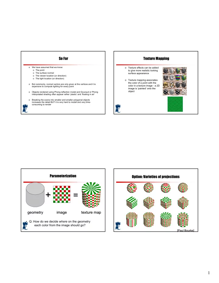
Parameterization geometry geometry

+ +

= =

image image texture map texture map

  • Q: How do we decide where on the geometry

each color from the image should go?

Option: Varieties of projections

[Paul Bourke] [Paul Bourke]

slide-2
SLIDE 2

2

Option: unfold the surface

[Piponi2000]

How to map object to texture?

  • To each vertex (x,y,z in object coordinates), must

associate 2D texture coordinates (s,t)

  • So texture fits “nicely” over object

Idea: Use Map Shape

  • Map shapes correspond to various projections
  • Planar, Cylindrical, Spherical
  • First, map (square) texture to basic map shape
  • Then, map basic map shape to object
  • Or vice versa: Object to map shape, map shape to square
  • Usually, this is straightforward
  • Maps from square to cylinder, plane, sphere well defined
  • Maps from object to these are simply spherical, cylindrical,

cartesian coordinate systems

Planar mapping

  • Like projections, drop z coord (s,t) = (x,y)
  • Problems: what happens near z = 0?
slide-3
SLIDE 3

3

Cylindrical Mapping

  • Cylinder: r, θ, z with (s,t) = (θ/(2π),z)
  • Note seams when wrapping around (θ = 0 or 2π)

Spherical Mapping

  • Convert to spherical coordinates: use latitude/long.
  • Singularities at north and south poles

Cube Mapping Cube Mapping

slide-4
SLIDE 4

4

Texture Mapping

  • Main Issues
  • How do we map between 3D
  • How does the texture modify the shading of pixels?
  • How do we sample the texture for a fragment?

Texture Mapping

  • Interpolation Texture Mapping (painting)
  • We need to define a mapping between the 3D world space (x,y,z)

and 2D image space (s,t)∈ [0,1]2

  • Texture coordinates defined at vertices serve this purpose
  • Specify (s,t) at each vertex:

V0 V1 V2

u v

Texture Mapping

  • Interpolate in the interior:

V0 V1 V2

Mapping the object on the left to the texture on the right u v

Texture Mapping

  • Interpolate in the interior:

V2(10,10) Consider the y value of 3 in the interpolation across the triangle. The rendering process determines that the range of object coordinates are from (3, 3) to (20, 3). The first co-ordinate comes from the interpolation along the left edge of the triangle at a parametric value t = 0.3. V0(0,0) V1(20, 3) (3, 3)

(0, 0) (50, 50) (100, 15) u v

slide-5
SLIDE 5

5

Texture Mapping

  • Interpolate in the interior:

V2(10,10) The texture location for this left edge location is (15, 15). Why? Object locations are interpolated from (3, 3) to (20, 3) Texture locations are interpolated from (15, 15) to (100, 15) V0(0,0) V1(20, 3) (3, 3)

(0, 0) (50, 50) (100, 15) (15, 15) u v

Texture Mapping

  • Interpolate in the interior:

V2(10,10) The texture gives a value that will influence the shading process. Specifically, the value from the texture replaces the diffuse constant in the calculation of the diffusion component in the illumination equation. By doing so, the texture values change the object appearance, but shape cues that come from the specular highlights will stay the same. V0(0,0) V1(20, 3) (3, 3)

(0, 0) (50, 50) (100, 15) (15, 15) u v

Texture Mapping

  • Interpolate in the interior:

V2(10,10) V0(0,0) V1(20, 3) (3, 3)

(0, 0) (50, 50) (100, 15) (15, 15) x y

( ) ( ) ( ) ( ) ( ) ( )

k r V R I K N L I v u Texture I K I k r V R I K N L I v u Texture I K I k r V R I K N L I v u Texture I K I

n i s i db a ab b n i s i dg a ag g n i s i dr a ar r

+

  • +
  • +

= +

  • +
  • +

= +

  • +
  • +

= ) , ( ) , ( ) , (

(u, v)

(x, y)

u v

Texture Mapping

  • Interpolate in the interior:

V2(10,10) V0(0,0) V1(20, 3) (3, 3)

(0, 0) (50, 50) (100, 15) (15, 15) x y (u, v)

(x, y)

A texture location can be calculated from object location directly. In general, mapping an object with x coordinates in the range from xmin to xmax and y coordinates in the range ymin to ymax into the texture coordinate range can be computed as: umin , umax , vmin , vmax are determined by the range of texture values assigned to the object vertices.

( ) ( )

min min max min max min min max min max

y y y y v v v x x x x u u u − − − = − − − =

u v

slide-6
SLIDE 6

6

Texture Mapping

  • Interpolate in the interior: - Painted texture
  • Simple
  • But can have problems – especially for highly irregular

surfaces

Artifacts

  • McMillan’s demo of this is at

http://graphics.lcs.mit.edu/classes/6.837/F98/Lecture21/Slide05.html

  • Another example

http://graphics.lcs.mit.edu/classes/6.837/F98/Lecture21/Slide06.html

  • What artifacts do you see?
  • Why?
  • Why not in standard Gouraud shading?
  • Hint: problem is in interpolating parameters

Interpolating Parameters

  • The problem turns out to be fundamental to interpolating

parameters in screen-space

  • Uniform steps in screen space ≠ uniform steps in world space

Texture Mapping

Linear interpolation

  • f texture coordinates

Correct interpolation with perspective divide

Hill Figure 8.42

slide-7
SLIDE 7

7

Interpolating Parameters

  • Perspective foreshortening is not getting applied to our

interpolated parameters

  • Parameters should be compressed with distance
  • Linearly interpolating them in screen-space doesn’t do this

Perspective-Correct Interpolation

  • Skipping a bit of math to make a long story short…
  • Rather than interpolating u and v directly, interpolate u/z and

v/z

  • These do interpolate correctly in screen space
  • Also need to interpolate z and multiply per-pixel
  • Problem: we don’t know z anymore
  • Solution: we do know w ∝ 1/z
  • So…interpolate uw and vw and w, and compute

u = uw/w and v = vw/w for each pixel

  • This unfortunately involves a divide per pixel
  • http://graphics.lcs.mit.edu/classes/6.837/F98/Lecture21/Slide14.html

Texture Map Filtering

  • Naive texture mapping aliases badly
  • Filtering

Moire pattern

Mapping to Curved Surfaces

s t x y z Xs Ys

Parametric surface x=x(u,v) y=y(u,v) z=z(u,v) A pixel A curved image The task is to map texture to surface, or to find a mapping u=as+bt+c v=ds+et+f

slide-8
SLIDE 8

8

Bump Mapping

  • This is another texturing technique
  • Aims to simulate a dimpled or wrinkled surface
  • for example, surface of an orange
  • Like Gouraud and Phong shading, it is a trick
  • surface stays the same
  • but the true normal is perturbed, to give the

illusion of surface ‘bumps’

How Does It Work?

  • Looking at it in 1D:
  • Original surface

P(u)

  • Bump map b(u)
  • Add b(u) to P(u)in

surface normal direction, N(u)

  • New surface

normal N’(u) for reflection model

Bump Mapping Example

Bump map Result

Bump Mapping Example

  • Texture = change in surface normal!

Sphere w/ diffuse texture Swirly bump map Sphere w/ diffuse texture and swirly bump map

slide-9
SLIDE 9

9

Illumination Maps

  • Quake introduced illumination maps or light maps to

capture lighting effects in video games

Texture map: Texture map + light map:

Light map

Environment Maps

Images from Illumination and Reflection Maps: Simulated Objects in Simulated and Real Environments Gene Miller and C. Robert Hoffman SIGGRAPH 1984 “Advanced Computer Graphics Animation” Course Notes