Geometric Optics www.njctl.org Slide 3 / 77 Slide 4 / 77 Table of - - PDF document

geometric optics
SMART_READER_LITE
LIVE PREVIEW

Geometric Optics www.njctl.org Slide 3 / 77 Slide 4 / 77 Table of - - PDF document

Slide 1 / 77 Slide 2 / 77 Geometric Optics www.njctl.org Slide 3 / 77 Slide 4 / 77 Table of Contents Click on the topic to go to that section Reflection Reflection Spherical Mirror Refraction and Snell's Law Thin Lenses


slide-1
SLIDE 1

Slide 1 / 77 Slide 2 / 77

www.njctl.org

Geometric Optics

Slide 3 / 77 Table of Contents

· Reflection

Click on the topic to go to that section

· Spherical Mirror · Refraction and Snell's Law · Thin Lenses

Slide 4 / 77

Reflection

Return to Table

  • f Contents

Slide 5 / 77 The Ray Model of Light

Light can travel in straight lines. We represent this using rays, which are straight lines emanating from a light source or object. This is really an idealization but it is very useful. For instance, you can see a pencil on a desk from any angle as long as there is nothing in your way. Light reflects off the pencil in all directions, which is represented by rays. You see the rays that hit your eye.

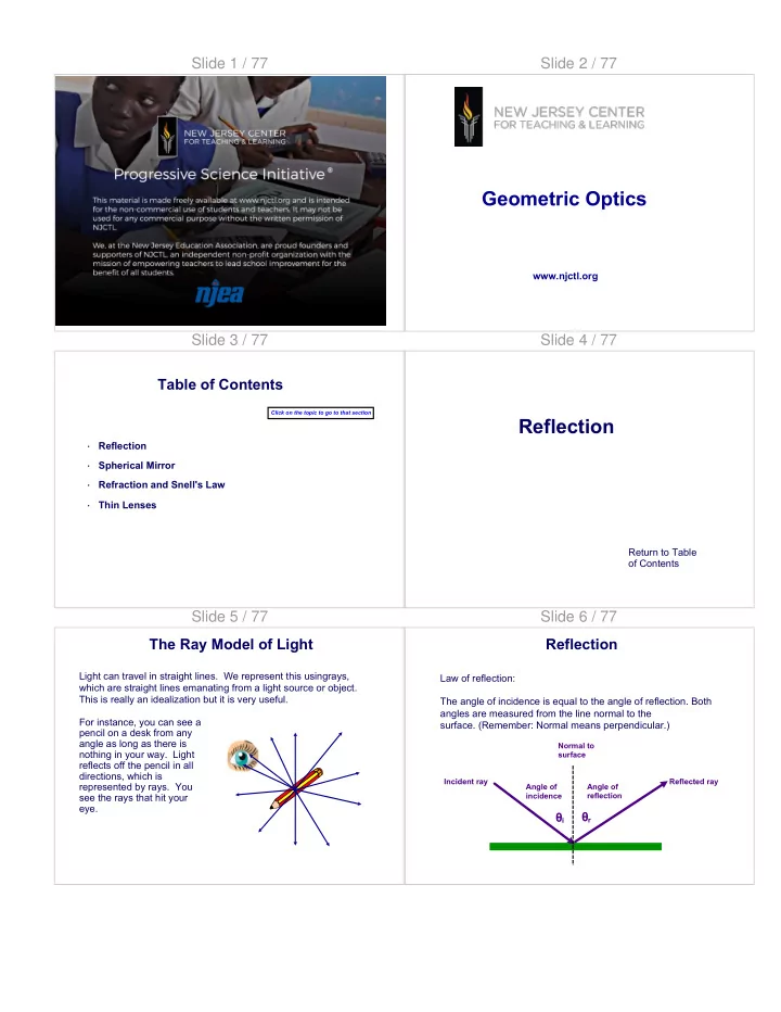
Slide 6 / 77 Reflection

Law of reflection: The angle of incidence is equal to the angle of reflection. Both angles are measured from the line normal to the

  • surface. (Remember: Normal means perpendicular.)

θi θr

Angle of incidence Angle of reflection Incident ray Reflected ray Normal to surface

slide-2
SLIDE 2

Slide 7 / 77 Reflection

When the light hits a rough surface and reflects, the law of reflection still holds but the angle of incidence varies so the light is diffused.

Slide 8 / 77 Reflection

With diffuse reflection, your eye sees reflected light at all angles but no image is really formed. With specular reflection (from a mirror) , your eye must be in the correct position. Both eyes see some reflected light. One eye sees reflected light the other does not.

Slide 9 / 77 Reflection

When you look into a plane (or flat) mirror, you see an image which appears to be behind the mirror. This is called a virtual image since the light does not go through it. The distance from the object to the mirror is the same as the distance from the mirror to the image. di do

Slide 10 / 77

1 The angle of reflection is ________ the angle of incidence. A less than B equal to C greater than

Slide 11 / 77

2 An object is placed in front of a plane mirror. Where is the image located? A B C D E Object

Slide 12 / 77

Spherical Mirror

Return to Table

  • f Contents
slide-3
SLIDE 3

Slide 13 / 77 Spherical Mirror

Spherical Mirrors are shaped like sections of a sphere and may be reflective on either the inside called concave (where parallel rays reflect and converge) or outside called convex (where parallel rays reflect and diverge).

Slide 14 / 77 Spherical Mirror

Rays coming in from a far away object are effectively parallel.

Slide 15 / 77 Spherical Mirror

For mirrors with large curvatures, parallel rays do not all converge at exactly the same point. This is called spherical aberration.

Slide 16 / 77 Spherical Mirror

If the curvature is small, the focus is much more precise. The focal point is where the rays converge. The focal length of a spherical mirror is half the radius of curvature. C f f r

Slide 17 / 77 Spherical Mirror

We can use ray diagrams to determine where the image will be when using a spherical mirror. We draw three principle rays:

  • 1. A ray that is first parallel to the axis and then, after

reflection, passes through the focal point.

  • 2. A ray that first passes through the focal point and then,

after reflection, is parallel to the axis.

  • 3. A ray perpendicular to the mirror and then reflects back
  • n itself.
  • 4. A ray that strikes the mirror at the principal axis (and a

certain angle) and reflects back (at the same angle).

Slide 18 / 77

C F

Spherical Mirror

  • 1. A ray that is first parallel to the axis and then, after

reflection, passes through the focal point.

slide-4
SLIDE 4

Slide 19 / 77

C F

Spherical Mirror

  • 2. A ray that first passes through the focal point and then,

after reflection, is parallel to the axis.

Slide 20 / 77

C F

  • 3. A ray perpendicular to the

mirror and then reflects back on

  • itself. (Note: this ray always goes through the center of curvature.)

Spherical Mirror Slide 21 / 77

C F

  • 4. A ray that strikes the mirror

at the principal axis (and a certain angle) and reflects back (at the same angle).

Spherical Mirror

Really, only two rays are needed to see where the image is located, but it is sometimes good to draw more.

Slide 22 / 77

C F We can derive an equation that relates the object distance, image distance, and focal length.

Spherical Mirror Slide 23 / 77

C F We can also derive an equation that relates the object distance, image distance, and magnification.

Spherical Mirror

The negative sign indicates that the image is inverted. (We do not need to use the negative sign because we can always draw a ray diagram and see if the image is inverted

  • r upright.)

Slide 24 / 77

C F This object is between the center of curvature and the focal point. Its image is magnified, real, and inverted.

Spherical Mirror

slide-5
SLIDE 5

Slide 25 / 77

C F If the object is past the center of curvature...

Spherical Mirror Slide 26 / 77

C F If the object is past the center of curvature... the image is de- magnified, real, and inverted.

Spherical Mirror Slide 27 / 77

C F If the object is inside the focal point...

Spherical Mirror Slide 28 / 77

C F If the object is inside the focal point... the image is magnified, virtual and upright. As you can see, if the rays do not intersect in real space, we must extended dotted lines backwards to form a virtual image

Spherical Mirror Slide 29 / 77

If the object is in front of the convex mirror...

Spherical Mirror

C F

Slide 30 / 77

If the object is in front of the convex mirror ... the image is de- magnified, virtual and upright.

Spherical Mirror

C F

slide-6
SLIDE 6

Slide 31 / 77

C F

3 A ray of light strikes a convex mirror parallel to the central axis. Which of the following represents the reflected ray? A B C D E

Slide 32 / 77

4 A candle is placed in front of a concave mirror between the center

  • f curvature and the focal point. The image is:

A real, inverted, and magnified. B real, inverted, and demagnified. C virtual, upright, and magnified. D virtual, upright, and demagnified. E real, upright, and magnified.

Slide 33 / 77

5 A candle with a height of 6 cm is placed 21 cm in front of a concave mirror with a focal length of 7 cm. How far is the image from the mirror?

Slide 34 / 77

6 A candle with a height 6 cm is placed 21 cm in front of a concave mirror with a focal length of 7 cm. How tall is the image?

Slide 35 / 77

7 Which of the following indicates the image distance, di, for an

  • bject that is placed in front of a concave mirror if the image

created is inverted? Select two answers. A do = f B 2f > do> f C do > 2f D f > do

Slide 36 / 77

Refraction and Snell's Law

Return to Table

  • f Contents
slide-7
SLIDE 7

Slide 37 / 77 Refraction and Snell's Law

As we saw in Electromagnetic Waves, light slows when traveling through a medium. The index of refraction (n) of the medium is the ratio of the speed of light in vacuum to the speed of light in the medium:

Slide 38 / 77 Refraction and Snell's Law

Light also changes direction when it enters a new medium. This is called refraction. The angle of incidence is related to the angle of

  • refraction. When the ray goes from less dense to more dense, it

bends towards the normal line and the refracted angle is smaller. When the ray goes from more dense to less dense, it bends away from the normal line and the refracted angle is larger.

Air (n1) Water (n

2)

Normal line

#1 #2

Reflected ray Incident ray Refracted ray Air (n2) Water (n

1)

Normal line

#2 #1

Reflected ray Incident ray Refracted ray

Slide 39 / 77 Refraction and Snell's Law

Air (n1) Water (n

2)

Normal line

#1 #2

Reflected ray Incident ray Refracted ray Air (n2) Water (n

1)

Normal line

#2 #1

Reflected ray Incident ray Refracted ray

n1 sin#1 = n2 sin#2

Slide 40 / 77 Refraction and Snell's Law

When light passes from air to a different medium back to air the ray that enters the medium is parallel to the ray that exits the medium. Using geometry, we can find the liner displacement between the emerging ray and the incident ray, if we know the angle of the incident ray and the thickness of the other medium.

Air (n1) Glass (n2)

#1 #2 #1 #2

Incident ray Emerging ray Incident ray Linear displacement

Slide 41 / 77 Refraction and Snell's Law

This is why objects look weird if they are partially under water.

Slide 42 / 77 Refraction and Snell's Law

If the incident angle is just big enough, the refracted ray will be parallel to the surface, so the refracted angle will be 90

  • . This

angel is called the critical angle.

Air (n2) Water (n

1)

Normal line

#2 #1

Incident ray Refracted ray

slide-8
SLIDE 8

Slide 43 / 77

Air (n2) Water (n

1)

Normal line

#C #1

Source

Refraction and Snell's Law

When the angle of incidence is larger than the critical angle, no light escapes the medium. This is called total internal reflection.

Slide 44 / 77 Refraction and Snell's Law

Remember that light both reflects and refracts when hitting a

  • surface. For example, see what happens to a ray of light at it

goes from glass to water to air. glass water air incident ray

reflected ray refracted ray

Slide 45 / 77

8 A ray of light bends _______ when going from air into glass. A towards the normal B away from the normal C not at all

Slide 46 / 77

9 A light ray incident on the surface of glass. Which of the follow represents the refracted ray? A B C D E

Slide 47 / 77

10 A ray of light passes from water to air at the critical angle. Which

  • f the following shows the refracted ray?

A B C D E

Slide 48 / 77

11 A light ray passes from substance A to substance B and exits substance B at point P. Where would the ray exit if the substance B was replaced with a material that has a lower index of refraction? A Above point P B At point P C Below point P D The location cannot be determined with out knowing the two indices of refraction. P

A B

slide-9
SLIDE 9

Slide 49 / 77

12 A substance has an index of refraction of 1.75. What is the critical angle for that substance in air?

Slide 50 / 77

Thin Lenses

Return to Table

  • f Contents

Slide 51 / 77 Thin Lenses

A thin lens is a lens whose thickness is small compared to its radius of curvature. Lenses can be converging or diverging. Converging lenses are thicker in the center than at the edges. Diverging lenses are thicker at the edges than in the center.

Slide 52 / 77 Thin Lenses

Converging lenses bring parallel rays to a focus which is the focal point. Diverging lenses make parallel light diverge. The focal point is the point where the rays would converge if the rays were projected back.

Slide 53 / 77 Thin Lenses and Ray Tracing

Ray tracing can be used to find the location and size of the image created by thin lenses as well as mirrors. They have similar steps.

  • 1. The first ray enters parallel to the axis and exits

through the focal point.

  • 2. The next ray enters through the focal point and then

exits parallel to the axis.

  • 3. The next ray goes through the center of the lens and

is not deflected.

Slide 54 / 77 Thin Lenses and Ray Tracing

  • 1. The first ray enters

parallel to the axis and exits through the focal point.

F F C C

slide-10
SLIDE 10

Slide 55 / 77 Thin Lenses and Ray Tracing

  • 2. The next ray enters

through the focal point and then exits parallel to the axis.

F F C C

Slide 56 / 77 Thin Lenses and Ray Tracing

  • 3. The next ray goes

through the center

  • f the lens and

is not deflected.

F F C C

Slide 57 / 77 Thin Lenses and Ray Tracing

Again, we only need two rays to see where the image is. When the object is between the focal point and center of curvature

  • f a converging lens, the image is magnified, real, and inverted.

F F C C

Slide 58 / 77 Thin Lenses and Ray Tracing

When the object is outside center of curvature...

F F C C

Slide 59 / 77 Thin Lenses and Ray Tracing

When the object is outside center of curvature... The image is de-magnified, real, and inverted.

F F C C

Slide 60 / 77 Thin Lenses and Ray Tracing

When the object is inside the focal point...

F F C C

slide-11
SLIDE 11

Slide 61 / 77 Thin Lenses and Ray Tracing

When the object is inside the focal point... The image is magnified, virtual, and upright.

F F C C

Note that when the rays do not converge on one side of the lens, they do on the other side.

Slide 62 / 77 Thin Lenses and Ray Tracing

For a diverging lens, when the object is between the focal point and the center of curvature...

F F C C

Slide 63 / 77 Thin Lenses and Ray Tracing

For a diverging lens, when the object is between the focal point and the center of curvature... The image is de-magnified, virtual, and upright.

F F C C

Slide 64 / 77 Thin Lenses and Ray Tracing

For a diverging lens, when the object is between the focal point and the center of curvature...

F F C C

Slide 65 / 77 Thin Lenses and Ray Tracing

For a diverging lens, when the object is between the focal point and the center of curvature... The image is de-magnified, virtual, and upright.

F F C C

Slide 66 / 77 Thin Lenses and Ray Tracing

For a diverging lens, when the object is past the center of curvature...

F F C C

slide-12
SLIDE 12

Slide 67 / 77 Thin Lenses and Ray Tracing

For a diverging lens, when the object is past the center of curvature... The image is de-magnified, virtual, and upright.

F F C C

Slide 68 / 77

The same equation that relates the object distance, image distance, and focal length for spherical mirrors, works for thin lenses.

Thin Lenses Slide 69 / 77

The same equation that relates the object distance, image distance, and magnification for mirrors, works for thin lenses.

Thin Lenses

It works for power as well. The power is positive if the lens is converging and negative if the lens is diverging.

Slide 70 / 77

The focal length is positive for converging lenses and negative for diverging lenses. The object distance is positive when it is on the same side at the light entering the lens and negative when it is on the

  • pposite side. (It is usually positive.)

The image distance is positive when it is a real image and negative when it is a virtual image. The height of the image is positive when it is upright and negative when it is inverted.

Thin Lenses: Sign Conventions Slide 71 / 77

13 Which of these lenses are diverging lenses? A I and V B II, III, and IV C II and III D III and IV E IV and V

Slide 72 / 77

14 An object is placed in front of a converging lens at a distance less then the focal length. The image is: A real, inverted, and demagnified. B real, inverted, and magnified. C virtual, upright, and magnified. D virtual, upright, and demagnified. E virtual, inverted, and magnified.

slide-13
SLIDE 13

Slide 73 / 77

15 An object is placed 10 cm in front of a converging lens with a focal length of 6 cm. How far is the image from the lens?

Slide 74 / 77

16 An object is placed 10 cm in front of a converging lens with a focal length of 6 cm. The object has a height if 5 cm. What is the height

  • f the image? (Use the answer to the previous question to answer

this one.)

Slide 75 / 77 Thin Lenses and Ray Tracing

For a combination of lenses...

F F C C Lens A Lens B F F C

Slide 76 / 77 Thin Lenses and Ray Tracing

For a combination of lenses... The image from the first lens becomes the object for the next.

F F C C Lens A Lens B F F C

Slide 77 / 77 Summary

Index of refraction: Focal length: Mirror/Lens Equation: Magnification: Snell's Law: n1 sin#1 = n2 sin#2