
SLIDE 1
General Purpose Processors
Calcolatori Elettronici e Sistemi Operativi
Specifications
Device that executes a program
Program
list of instructions
Instructions are stored in an external memory
Stored program
Data can be read and written from/to an external memory
Universal computation
approximate
finite storage
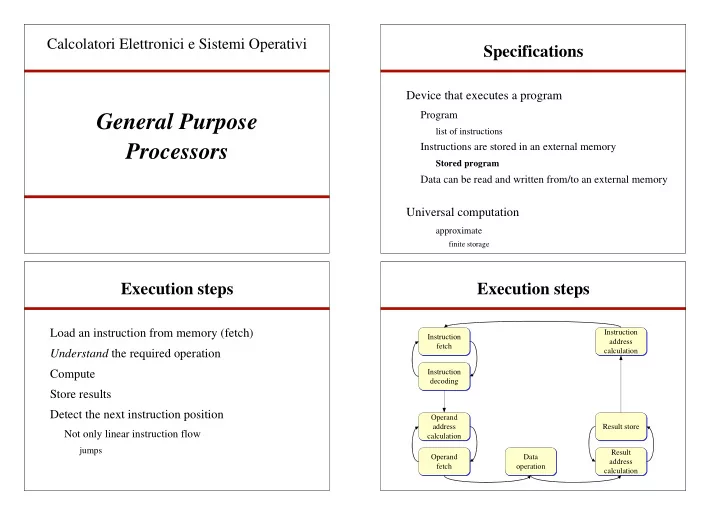
Execution steps
Load an instruction from memory (fetch) Understand the required operation Compute Store results Detect the next instruction position
Not only linear instruction flow
jumps
Execution steps
Instruction fetch Instruction fetch Instruction decoding Instruction decoding Operand address calculation Operand address calculation Operand fetch Operand fetch Data
- peration
Data
- peration
Result store Result store Result address calculation Result address calculation Instruction address calculation Instruction address calculation