fuel performance analysis of advanced ferritic steel
play

Fuel Performance Analysis of Advanced Ferritic Steel Cladding for - PDF document

Transactions of the Korean Nuclear Society Virtual Spring Meeting July 9-10, 2020 Fuel Performance Analysis of Advanced Ferritic Steel Cladding for Accident Tolerant Fuel J. H. Kim , C. D. Jung , H. Jang, C. Lim KEPCO Nuclear Fuel, 242,


  1. Transactions of the Korean Nuclear Society Virtual Spring Meeting July 9-10, 2020 Fuel Performance Analysis of Advanced Ferritic Steel Cladding for Accident Tolerant Fuel J. H. Kim ∗ , C. D. Jung , H. Jang, C. Lim KEPCO Nuclear Fuel, 242, Daeduk-daero 989beon-gil, Yuseong-gu, Daejeon, Korea, * Corresponding author: jhk@knfc.co.kr 1. Introduction The cladding thickness was reduced from 0.57 mm to 0.35 mm, and the pellet outer diameter was increased from 8.192 mm to 8.632 mm to maintain the same gap Since 2017, KEPCO NF has started to research and size between pellet and cladding. Reduced cladding develop Advanced Ferritic Steel (AFS) [1], which is thickness and increased fuel mass can compensate the considered as a candidate alloy for accident tolerant fuel neutronics. However, fuel pellet were unchanged and U- (ATF) cladding to replace the existing Zr-based alloy 
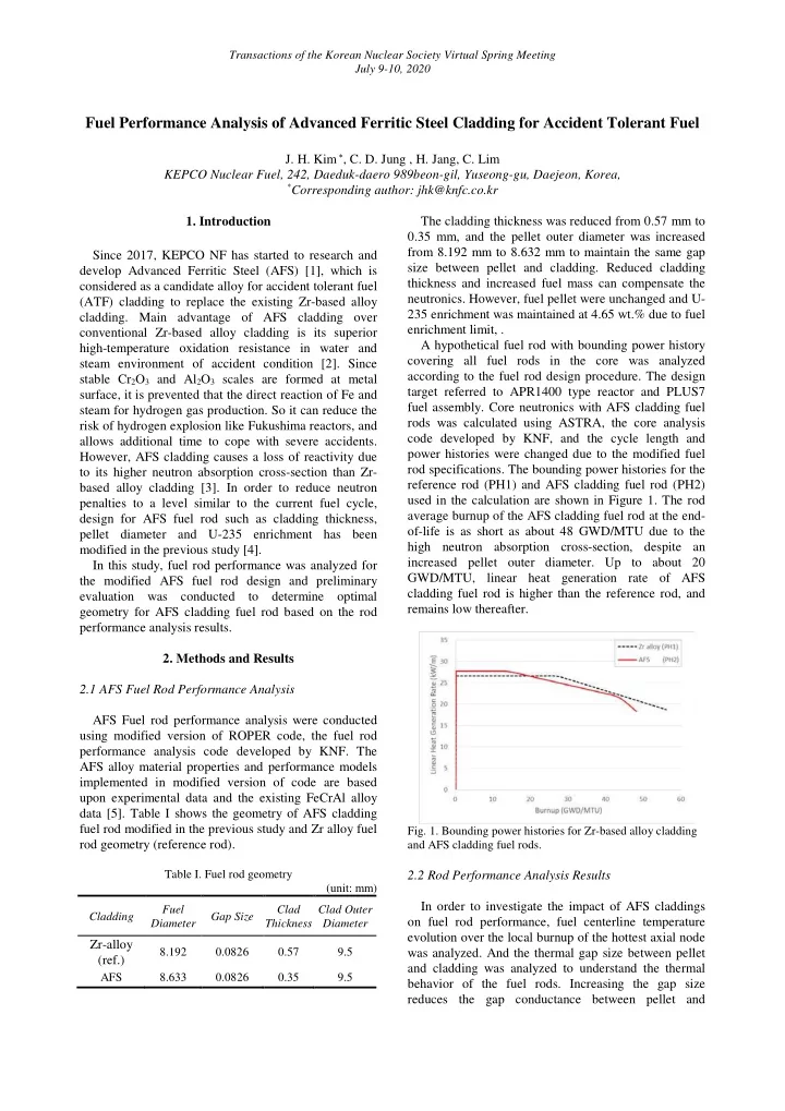
235 enrichment was maintained at 4.65 wt.% due to fuel cladding. Main advantage of AFS cladding over enrichment limit, . conventional Zr-based alloy cladding is its superior A hypothetical fuel rod with bounding power history high-temperature oxidation resistance in water and covering all fuel rods in the core was analyzed steam environment of accident condition [2]. Since according to the fuel rod design procedure. The design stable Cr 2 O 3 and Al 2 O 3 scales are formed at metal target referred to APR1400 type reactor and PLUS7 surface, it is prevented that the direct reaction of Fe and fuel assembly. Core neutronics with AFS cladding fuel steam for hydrogen gas production. So it can reduce the rods was calculated using ASTRA, the core analysis risk of hydrogen explosion like Fukushima reactors, and code developed by KNF, and the cycle length and allows additional time to cope with severe accidents. power histories were changed due to the modified fuel However, AFS cladding causes a loss of reactivity due rod specifications. The bounding power histories for the to its higher neutron absorption cross-section than Zr- reference rod (PH1) and AFS cladding fuel rod (PH2) based alloy cladding [3]. In order to reduce neutron used in the calculation are shown in Figure 1. The rod penalties to a level similar to the current fuel cycle, average burnup of the AFS cladding fuel rod at the end- design for AFS fuel rod such as cladding thickness, of-life is as short as about 48 GWD/MTU due to the pellet diameter and U-235 enrichment has been high neutron absorption cross-section, despite an modified in the previous study [4]. increased pellet outer diameter. Up to about 20 In this study, fuel rod performance was analyzed for GWD/MTU, linear heat generation rate of AFS the modified AFS fuel rod design and preliminary cladding fuel rod is higher than the reference rod, and evaluation was conducted to determine optimal remains low thereafter. geometry for AFS cladding fuel rod based on the rod performance analysis results. 2. Methods and Results 2.1 AFS Fuel Rod Performance Analysis AFS Fuel rod performance analysis were conducted using modified version of ROPER code, the fuel rod performance analysis code developed by KNF. The AFS alloy material properties and performance models implemented in modified version of code are based upon experimental data and the existing FeCrAl alloy data [5]. Table I shows the geometry of AFS cladding fuel rod modified in the previous study and Zr alloy fuel Fig. 1. Bounding power histories for Zr-based alloy cladding rod geometry (reference rod). and AFS cladding fuel rods. Table I. Fuel rod geometry 2.2 Rod Performance Analysis Results (unit: mm) In order to investigate the impact of AFS claddings Fuel Clad Clad Outer Cladding Gap Size on fuel rod performance, fuel centerline temperature Diameter Thickness Diameter evolution over the local burnup of the hottest axial node Zr-alloy 8.192 0.0826 0.57 9.5 was analyzed. And the thermal gap size between pellet (ref.) and cladding was analyzed to understand the thermal AFS 8.633 0.0826 0.35 9.5 behavior of the fuel rods. Increasing the gap size reduces the gap conductance between pellet and

  2. Transactions of the Korean Nuclear Society Virtual Spring Meeting July 9-10, 2020 cladding, which leads to an increase in pellet temperature. It is difficult to directly compare the Figure 4 displays the cladding mid-wall hoop stress. performance of two claddings using different power The hoop stress of reference fuel cladding is changed histories, but the general behavior anticipated in a core from compressive to tensile near 25 GWD/MTU, at can be predicted. Further calculation for AFS cladding which point the mechanical gap is completely closed, as fuel rod assuming the same cycle length and bounding shown in Figure 3. On the other hand, the hoop stress of power with reference rod (AFS with PH1) was carried AFS claddings are remained compressive because the out additionally to compare two cladding materials mechanical gap is not closed until the end-of-life, under the same conditions. regardless of the power history. Fuel centerline temperature of reference rod decreases rapidly (~100 ℃ ) as the thermal gap closes in the early stage of operation, as shown in Figure 2. After the thermal gap closure, temperature gradually increases due to the effect of pellet thermal conductivity degradation (TCD), and then finally decreases again as the power decreases. AFS with PH1 also has a similar behavior, except that the gap closes slowly compared to reference rod as shown in Figure 3. Because of the higher creep resistance of AFS cladding, there is less deformation due to the coolant pressure, which leads to a later gap closure despite the higher amount of pellet thermal expansion. Due to late thermal gap closure, fuel Fig. 4. AFS cladding mid-wall hoop stress vs. local burnup centerline temperature is higher (~130 ℃ ) than reference rod in low-burnup region (~20 GWD/MTU). 2.3 Fuel Rod Geometry Optimization This indicates that the stored energy of fuel is high, which means that there may be a shortage of thermal As a result of the fuel rod performance analysis, there margin under accident conditions. Compared to this, is a problem that the centerline temperature of AFS fuel AFS with PH2 shows even higher temperature in low- rod is higher (~130 ℃ ) than reference rod in the low- burnup region and lower in later, which is consistent burnup region (~20 GWD/MTU). This occurs because with the difference shown in bounding power. the gap size of AFS fuel rod decreases slowly compared to reference rod, so that heat transfer between pellet and cladding is poor in low-burnup region. In the previous calculations, initial gap size of AFS fuel rod was same with reference rod, so we can consider reducing initial gap size of AFS fuel rod to lower the fuel temperature in the low-burnup region. Reducing the initial gap size while maintaining the fuel rod outer diameter makes the pellet outer diameter slightly larger. Two additional cases ‒ AFS case1 and AFS case2 ‒ were calculated for initial gap size optimization, and the fuel rod geometries in each case are shown in Table II. Table II. Fuel rod geometry for gap size optimization Fig. 2. AFS fuel centerline temperature vs. local burnup (unit: mm) Fuel Clad Clad Outer Case Gap Size Diameter Thickness Diameter Zr-based 0.0826 8.192 0.57 9.5 (3.25 mil) alloy AFS 0.0826 8.633 0.35 9.5 base case (3.25 mil) 0.0762 AFS case1 8.646 0.35 9.5 (3.00 mil) 0.0699 AFS case2 8.659 0.35 9.5 (2.75 mil) Fig. 3. AFS fuel mechanical and thermal gap between pellet and cladding vs. local burnup

Download Presentation
Download Policy: The content available on the website is offered to you 'AS IS' for your personal information and use only. It cannot be commercialized, licensed, or distributed on other websites without prior consent from the author. To download a presentation, simply click this link. If you encounter any difficulties during the download process, it's possible that the publisher has removed the file from their server.

Recommend


More recommend