
Fuel Cell System Based On Boost Inverter For Single Phase Grid Integration Using ANN
K.V.Sneha
M-Tech Student Department of Electrical & Electronics Engineering Vimal Jyothi Engineering College,Kannur,Kerala,India snehakv326@gmail.com
Nikhil Valsan K.
Assistant Professor Department of Electrical & Electronics Engineering Vimal Jyothi Engineering College,Kannur,Kerala,India nikhilvalsan88@gmail.com Abstract—Alternative energy sources, such as solar and fuel
cells are desirable due to their pollution-free property. To utilize the current infrastructure of the grid for power transmission and distribution, grid-connected dc-to-ac inverters are needed.When a low-voltage unregulated fuel-cell (FC) output is conditioned to generate the ac power, two stages are required: a boost stage and an inversion one. Here the boost-inverter topology that achieves both boosting and inversion functions in a single-stage is used as a building block. It is used to develop a single-phase grid- connected FC-system which offers high conversion efficiency, low-cost and compactness.In addition, this system incorporates battery-based energy storage and a bidirectional dc-dc converter to support the slow dynamics of FC. The single-phase boost inverter is voltage-mode controlled and the bidirectional dc-dc converter is current-mode controlled. Artificial neural network is used here as the controller. The battery supplies the low- frequency current ripple which minimizes the effects of such ripple being drawn directly from the FC itself. Also, this system can operate either in a grid-connected or stand-alone mode. Simulation results are presented to confirm the performance of the proposed system. Keywords—Boost inverter, fuel cell(FC), grid-connected inverter, PQ control
I. INTRODUCTION Energy sources such as wind power systems, photovoltaic cells, and fuel cells have been extensively studied in response to global warming and environmental issues. For conditioning
- f both ac and dc loads,we can use alternative energy
generation systems based on solar photovoltaics and fuel cells (FCs) . Also, size reduction and high efficiency are essential
- requirements. To achieve high-quality supply of power, the
FC systems must be assisted by additional energy storage unit. An inversion stage is also required to power ac loads or to connect to the electricity grid when such systems are used. The typical output voltage of low-power FC is low and variable on the load current. Due to the operation of components such as pumps, heat exchangers, and fuel- processing unit, the hydrogen and oxidant cannot respond the load current changes instantaneously. There will be cold-start which takes more than few seconds[1]. A two-stage FC power conditioning system to deliver ac power has been described. It encounters drawbacks such as being bulky and relatively inefficient. To alleviate these disadvantages, a topology that is suitable for ac loads and is powered from dc sources able to boost and invert the voltage at the same time has been proposed in [3]. The double loop control scheme of this topology has been proposed[4].A single-stage FC system based on a boost inverter has been proposed in[2], [5]. The aim of this paper is to introduce a grid-connected single-phase FC system using a single energy conversion stage
- nly and also to present the simulation results. In particular,
the proposed system, based on the boost inverter with a backup energy storage unit, solves the earlier mentioned
- issues. This single-stage including boosting and inversion
functions provide a high power conversion efficiency, reduced converter size and low cost. The proposed single-phase grid- connected FC system can operate either in grid-connected or stand-alone mode. Here neural network is used as the controller. Neural network has capabilities to approximate any nonlinear function relationship and more convenient learning means.
- II. PROPOSED FC ENERGY SYSTEM
- A. Description of the FC System
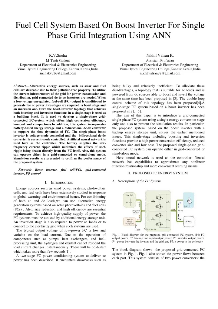
- Fig. 1. Block diagram for the proposed grid-connected FC system. (P1: FC
- utput power, P2: backup unit input/output power, P3: inverter output power,
P4: power between the inverter and the grid, and P5: a power to the ac loads)
The block diagram shows the proposed grid-connected FC system in Fig. 1. Fig. 1 also shows the power flows between each part. This system consists of two power converters: the