From 3D to 2D: Orthographic and Perspective ProjectionPart 1 - - PDF document

from 3d to 2d orthographic and perspective projection
SMART_READER_LITE
LIVE PREVIEW

From 3D to 2D: Orthographic and Perspective ProjectionPart 1 - - PDF document

I N T R O D U C T I O N T O C O M P U T E R G R A P H I C S I N T R O D U C T I O N T O C O M P U T E R G R A P H I C S From 3D to 2D: Orthographic and Perspective ProjectionPart 1 History Geometrical


slide-1
SLIDE 1

1

I N T R O D U C T I O N T O C O M P U T E R G R A P H I C S

Andries van Dam September 15, 2005 3D Viewing I

3D Viewing I

I N T R O D U C T I O N T O C O M P U T E R G R A P H I C S

Andries van Dam September 15, 2005 3D Viewing I 1/38

  • History
  • Geometrical Constructions
  • Types of Projection
  • Projection in Computer Graphics

From 3D to 2D: Orthographic and Perspective Projection—Part 1

I N T R O D U C T I O N T O C O M P U T E R G R A P H I C S

Andries van Dam September 15, 2005 3D Viewing I 2/38

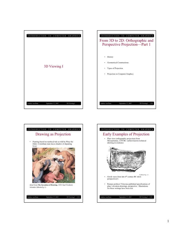
  • Painting based on mythical tale as told by Pliny the

Elder: Corinthian man traces shadow of departing lover

detail from The Invention of Drawing, 1830: Karl Friedrich Schinkle (Mitchell p.1)

Drawing as Projection

I N T R O D U C T I O N T O C O M P U T E R G R A P H I C S

Andries van Dam September 15, 2005 3D Viewing I 3/38

  • Plan view (orthographic projection) from

Mesopotamia, 2150 BC: earliest known technical drawing in existence

  • Greek vases from late 6th century BC show

perspective(!)

  • Roman architect Vitruvius published specifications of

plan / elevation drawings, perspective. Illustrations for these writings have been lost

Early Examples of Projection

Carlbom Fig. 1-1

slide-2
SLIDE 2

2

I N T R O D U C T I O N T O C O M P U T E R G R A P H I C S

Andries van Dam September 15, 2005 3D Viewing I 4/38

  • || lines converge (in 1, 2, or 3 axes) to vanishing point
  • Objects farther away are more foreshortened

(i.e., smaller) than closer ones

  • Example: perspective cube

Most Striking Features of Linear Perspective

edges same size, with farther ones smaller parallel edges converging I N T R O D U C T I O N T O C O M P U T E R G R A P H I C S

Andries van Dam September 15, 2005 3D Viewing I 5/38

  • Ways of invoking three dimensional space: shading

suggests rounded, volumetric forms; converging lines suggest spatial depth of room

  • Not systematic—lines do not converge to single

vanishing point

Early Perspective

Giotto, Franciscan Rule Approved, Assisi, Upper Basilica, c.1295-1300 I N T R O D U C T I O N T O C O M P U T E R G R A P H I C S Andries van Dam September 15, 2005 3D Viewing I 6/38

  • The Renaissance: new emphasis on importance of

individual viewpoint and world interpretation, power

  • f observation—particularly of nature (astronomy,

anatomy, botany, etc.)

– Massaccio – Donatello – Leonardo – Newton

  • Universe as clockwork: intellectual rebuilding of

universe along mechanical lines

Setting for “Invention” of Perspective Projection

Ender, Tycho Brahe and Rudolph II in Prague (detail of clockwork), c. 1855 url: http://www.mhs.ox.ac.uk/tycho/catfm.htm?image10a

I N T R O D U C T I O N T O C O M P U T E R G R A P H I C S

Andries van Dam September 15, 2005 3D Viewing I 7/38

  • Brunelleschi invented systematic method of

determining perspective projections (early 1400’s). Evidence that he created demonstration panels, with specific viewing constraints for complete accuracy of

  • reproduction. Note the perspective is accurate only

from one POV (see Last Supper)

  • Vermeer created perspective boxes where picture,

when viewed through viewing hole, had correct perspective

  • Vermeer on the web:

– http://www.grand-illusions.com/vermeer/vermeer1.htm – http://essentialvermeer.20m.com/ – http://brightbytes.com/cosite/what.html

Brunelleschi and Vermeer

Vermeer, The Music Lesson, c.1662-1665 (left) and reconstruction (center)

slide-3
SLIDE 3

3

I N T R O D U C T I O N T O C O M P U T E R G R A P H I C S

Andries van Dam September 15, 2005 3D Viewing I 8/38

  • An artist named David Hockney proposed that many

Renaissance artists, including Vermeer, might have been aided by camera obscura while painting their masterpieces, raising a big controversy

  • David Stork, a Stanford optics expert, refuted Hockney’s

claim in the heated 2001 debate about the subject among artists, museum curators and scientists. He also wrote the article “Optics and Realism in Renaissance Art”, using scientific techniques to disprove Hockney’s theory

Hockney and Stork

Hockney, D. (2001) Secret Knowledge: Rediscovering the Lost Techniques of the Old

  • Masters. New York: Viking Studio.

Stork, D. (2004) Optics and Realism in Renaissance Art. Scientific American 12, 52-59.

I N T R O D U C T I O N T O C O M P U T E R G R A P H I C S

Andries van Dam September 15, 2005 3D Viewing I 9/38

  • Published first treatise on perspective, Della Pittura,

in 1435

  • “A painting [the projection plane] is the intersection
  • f a visual pyramid [view volume] at a given

distance, with a fixed center [center of projection] and a defined position of light, represented by art with lines and colors on a given surface [the rendering].” (Leono Battista Alberti (1404-1472), On Painting, pp. 32-33)

Alberti

I N T R O D U C T I O N T O C O M P U T E R G R A P H I C S

Andries van Dam September 15, 2005 3D Viewing I 10/38

  • Projected image is easy to calculate based on

– height of object (AB) – distance from eye to object (CB) – distance from eye to picture (projection) plane (CD) – and using relationship CB: CD as AB: ED

  • AB is component of A’ in the plane of projection

The Visual Pyramid and Similar Triangles

CB : CD as AB : ED

  • bject

picture plane projected object

I N T R O D U C T I O N T O C O M P U T E R G R A P H I C S

Andries van Dam September 15, 2005 3D Viewing I 11/38

  • Concept of similar triangles described both

geometrically and mechanically in widely read treatise by Albrecht Dürer (1471-1528)

Dürer

Albrecht Dürer, Artist Drawing a Lute Woodcut from Dürer’s work about the Art of Measurement. ‘Underweysung der messung’, Nurenberg, 1525

slide-4
SLIDE 4

4

I N T R O D U C T I O N T O C O M P U T E R G R A P H I C S

Andries van Dam September 15, 2005 3D Viewing I 12/38

  • Point of view influences content and meaning of what

is seen

  • Are royal couple in mirror about to enter room? Or is

their image a reflection of painting on far left?

  • Analysis through computer reconstruction of the

painted space

– verdict: royal couple in mirror is reflection from canvas in foreground, not reflection of actual people (Kemp

  • pp. 105-108)

Las Meninas (1656) by Diego Velàzquez

I N T R O D U C T I O N T O C O M P U T E R G R A P H I C S

Andries van Dam September 15, 2005 3D Viewing I 13/38

Robert Campin The Annunciation Triptych (ca. 1425)

I N T R O D U C T I O N T O C O M P U T E R G R A P H I C S

Andries van Dam September 15, 2005 3D Viewing I 14/38

  • Perspective can be used in unnatural ways to control

perception

  • Use of two viewpoints concentrates viewer’s

attention alternately on Christ and sarcophagus

Piero della Francesca The Resurrection (1460)

I N T R O D U C T I O N T O C O M P U T E R G R A P H I C S

Andries van Dam September 15, 2005 3D Viewing I 15/38

  • Perspective plays very large

role in this painting

Leonardo da Vinci The Last Supper (1495)

slide-5
SLIDE 5

5

I N T R O D U C T I O N T O C O M P U T E R G R A P H I C S

Andries van Dam September 15, 2005 3D Viewing I 16/38

  • 2 point perspective—two vanishing points

Geometrical Construction of Projections

from Vredeman de Vries’s Perspective, Kemp p.117 I N T R O D U C T I O N T O C O M P U T E R G R A P H I C S

Andries van Dam September 15, 2005 3D Viewing I 17/38

  • Projectors are straight lines
  • Projection surface is plane (picture plane, projection

plane)

  • This drawing itself is perspective projection
  • What other types of projections do you know?

– hint: maps

Planar Geometric Projection

projectors eye, or Center of Projection (COP) projectors picture plane I N T R O D U C T I O N T O C O M P U T E R G R A P H I C S

Andries van Dam September 15, 2005 3D Viewing I 18/38

a) Perspective: determined by Center of Projection (COP) (in our diagrams, the “eye”) b) Parallel: determined by Direction of Projection (DOP) (projectors are parallel—do not converge to “eye” or COP). Alternatively, COP is at

  • In general, a projection is determined by where

you place the projection plane relative to principal axes of object (relative angle and position), and what angle the projectors make with the projection plane

Main Classes of Planar Geometrical Projections

I N T R O D U C T I O N T O C O M P U T E R G R A P H I C S

Andries van Dam September 15, 2005 3D Viewing I 19/38

Types of Projection

slide-6
SLIDE 6

6

I N T R O D U C T I O N T O C O M P U T E R G R A P H I C S

Andries van Dam September 15, 2005 3D Viewing I 20/38

  • Parallel projections used for engineering and

architecture because they can be used for measurements

  • Perspective imitates eyes or camera and looks more

natural

Logical Relationship Between Types of Projections

I N T R O D U C T I O N T O C O M P U T E R G R A P H I C S

Andries van Dam September 15, 2005 3D Viewing I 21/38

  • Used for:

– engineering drawings of machines, machine parts – working architectural drawings

  • Pros:

– accurate measurement possible – all views are at same scale

  • Cons:

– does not provide “realistic” view or sense of 3D form

  • Usually need multiple views to get a three-

dimensional feeling for object

Multiview Orthographic

I N T R O D U C T I O N T O C O M P U T E R G R A P H I C S

Andries van Dam September 15, 2005 3D Viewing I 22/38

  • Same method as multiview
  • rthographic projections, except

projection plane not parallel to any of coordinate planes; parallel lines equally foreshortened

  • Isometric: Angles between all

three principal axes equal (120º). Same scale ratio applies along each axis

  • Dimetric: Angles between two
  • f the principal axes equal;

need two scale ratios

  • Trimetric: Angles different

between three principal axes; need three scale ratios

  • Note: different names for

different views, but all part of a continuum of parallel projections of cube; these differ in where projection plane is relative to its cube

Axonometric Projections

I N T R O D U C T I O N T O C O M P U T E R G R A P H I C S

Andries van Dam September 15, 2005 3D Viewing I 23/38

  • Used for:

– catalogue illustrations – patent office records – furniture design – structural design

  • Pros:

– don’t need multiple views – illustrates 3D nature of object – measurements can be made to scale along principal axes

  • Cons:

– lack of foreshortening creates distorted appearance – more useful for rectangular than curved shapes

Isometric Projection (1/2)

Construction of an isometric projection: projection plane cuts each principal axis by 45°

slide-7
SLIDE 7

7

I N T R O D U C T I O N T O C O M P U T E R G R A P H I C S

Andries van Dam September 15, 2005 3D Viewing I 24/38

Isometric Projection (2/2)

  • Video games have been using isometric projection for ages.

It all started in 1982 with Q*Bert and Zaxxon which were made possible by advances in raster graphics hardware

  • Still in use today when you want to see things in distance as

well as things close up (e.g. strategy, simulation games)

  • Technically some games today aren’t isometric and are instead axonometric,

but people still call them isometric to avoid learning a new word. Other inappropriate terms used for axonometric views are “2.5D” and “three- quarter.”

I N T R O D U C T I O N T O C O M P U T E R G R A P H I C S

Andries van Dam September 15, 2005 3D Viewing I 25/38

  • Projectors at oblique angle to projection plane; view

cameras have accordion housing, used for skyscrapers

  • Pros:

– can present exact shape of one face of an object (can take accurate measurements): better for elliptical shapes than axonometric projections, better for “mechanical” viewing – lack of perspective foreshortening makes comparison

  • f sizes easier

– displays some of object’s 3D appearance

  • Cons:

  • bjects can look distorted if careful choice not made

about position of projection plane (e.g., circles become ellipses) – lack of foreshortening (not realistic looking)

Oblique Projections

  • blique

perspective I N T R O D U C T I O N T O C O M P U T E R G R A P H I C S

View Camera

source: http://www.usinternet.com/users/rniederman/star01.htm

Andries van Dam September 15, 2005 3D Viewing I 26/38

I N T R O D U C T I O N T O C O M P U T E R G R A P H I C S

Andries van Dam September 15, 2005 3D Viewing I 27/38

Examples of Oblique Projections

Construction of

  • blique parallel projection

Plan oblique projection of city Front oblique projection of radio

(Carlbom Fig. 2-4)

slide-8
SLIDE 8

8

I N T R O D U C T I O N T O C O M P U T E R G R A P H I C S

Andries van Dam September 15, 2005 3D Viewing I 28/38

  • Rules for placing projection plane for oblique views:

projection plane should be chosen according to one or several of following:

– parallel to most irregular of principal faces, or to one which contains circular or curved surfaces – parallel to longest principal face of object – parallel to face of interest

Example: Oblique View

Projection plane parallel to circular face Projection plane not parallel to circular face I N T R O D U C T I O N T O C O M P U T E R G R A P H I C S

Andries van Dam September 15, 2005 3D Viewing I 29/38

  • Cavalier: Angle between projectors and projection

plane is 45º. Perpendicular faces projected at full scale

  • Cabinet: Angle between projectors & projection

plane: arctan(2) = 63.4º. Perpendicular faces projected at 50% scale

Main Types of Oblique Projections

cavalier projection

  • f unit cube

cabinet projection

  • f unit cube

I N T R O D U C T I O N T O C O M P U T E R G R A P H I C S

Andries van Dam September 15, 2005 3D Viewing I 30/38

Examples of Orthographic and Oblique Projections

multiview orthographic cavalier cabinet

  • yyyyyyy
y y
  • yyyyyyy
y y
  • yyyyyyy
y y
  • yyyyyyy
y y
  • y
y y y y y y y y y
  • y
y y y y y y y y y
  • y
y y y y y y y y y
  • y
y y y y y y y y y

I N T R O D U C T I O N T O C O M P U T E R G R A P H I C S

Andries van Dam September 15, 2005 3D Viewing I 31/38

  • Assume object face of interest lies in principal plane,

i.e., parallel to xy, yz, or zx planes. (DOP = Direction

  • f Projection, VPN = View Plane Normal)

Summary of Parallel Projections

1) Multiview Orthographic

– VPN || a principal coordinate axis – DOP || VPN – shows single face, exact measurements

2) Axonometric

– VPN || a principal coordinate axis – DOP || VPN – adjacent faces, none exact, uniformly foreshortened (function

  • f angle between face normal and

DOP)

3) Oblique

– VPN || a principal coordinate axis – DOP || VPN – adjacent faces, one exact, others uniformly foreshortened

slide-9
SLIDE 9

9

I N T R O D U C T I O N T O C O M P U T E R G R A P H I C S

Andries van Dam September 15, 2005 3D Viewing I 32/38

  • Used for:

– advertising – presentation drawings for architecture, industrial design, engineering – fine art

  • Pros:

– gives a realistic view and feeling for 3D form of object

  • Cons:

– does not preserve shape of object or scale (except where object intersects projection plane)

  • Different from a parallel projection because

– parallel lines not parallel to the projection plane converge – size of object is diminished with distance – foreshortening is not uniform

Perspective Projections

I N T R O D U C T I O N T O C O M P U T E R G R A P H I C S

y x z y x z

Andries van Dam September 15, 2005 3D Viewing I 33/38

  • For right-angled forms whose face normals are

perpendicular to the x, y, z coordinate axes, number of vanishing points = number of principal coordinate axes intersected by projection plane

Vanishing Points (1/2)

Three Point Perspective (z, x, and y-axis vanishing points) Two Point Perspective (z, and x-axis vanishing points) One Point Perspective (z-axis vanishing point)

y z x y x z y x y x z z

I N T R O D U C T I O N T O C O M P U T E R G R A P H I C S

Andries van Dam September 15, 2005 3D Viewing I 34/38

  • What happens if same form is turned so its face normals are

not perpendicular to x, y, z coordinate axes?

Vanishing Points (2/2)

  • Although projection plane only intersects one axis (z), three

vanishing points created

  • But… can achieve final results identical to previous situation

in which projection plane intersected all three axes

  • New viewing situation: cube

is rotated, face normals no longer perpendicular to any principal axes

Perspective drawing

  • f the rotated cube

Unprojected cube depicted here with parallel projection

I N T R O D U C T I O N T O C O M P U T E R G R A P H I C S

Andries van Dam September 15, 2005 3D Viewing I 35/38

  • We’ve seen two pyramid geometries for

understanding perspective projection:

  • Combining these 2 views:

Vanishing Points and the View Point (1/3)

1. perspective image is intersection of a plane with light rays from

  • bject to eye (COP)

2. perspective image is result of foreshortening due to convergence of some parallel lines toward vanishing points

slide-10
SLIDE 10

10

I N T R O D U C T I O N T O C O M P U T E R G R A P H I C S

Andries van Dam September 15, 2005 3D Viewing I 36/38

  • Project parallel lines AB, CD on xy plane
  • Projectors from eye to AB and CD define two planes,

which meet in a line which contains the view point, or eye

  • This line does not intersect projection plane (XY),

because parallel to it. Therefore there is no vanishing point

Vanishing Points and the View Point (2/3)

I N T R O D U C T I O N T O C O M P U T E R G R A P H I C S

Andries van Dam September 15, 2005 3D Viewing I 37/38

  • Lines AB and CD (this time with A and C behind the

projection plane) projected on xy plane: A’B and C’D

  • Note: A’B not parallel to C’D
  • Projectors from eye to A’B and C’D define two planes

which meet in a line which contains the view point

  • This line does intersect projection plane
  • Point of intersection is vanishing point

Vanishing Points and the View Point (3/3)

I N T R O D U C T I O N T O C O M P U T E R G R A P H I C S

Andries van Dam September 15, 2005 3D Viewing I 38/38

Next Time: Projection in Computer Graphics