Flicker Stereo: volves allowing only one image to enter each eye - - PDF document

flicker stereo
SMART_READER_LITE
LIVE PREVIEW

Flicker Stereo: volves allowing only one image to enter each eye - - PDF document

Downloaded from https://www.cambridge.org/core. IP address: 192.151.151.66, on 18 Aug 2020 at 17:19:18, subject to the Cambridge Core terms of use, available at https://www.cambridge.org/core/terms. https://doi.org/10.1017/S1551929500056315


slide-1
SLIDE 1

Flicker Stereo: Digital 3D Viewing for PC & Presentation

Nathan R. Greenhut* and Victor A. Greenhut**

* Industrial & Systems Engineering, Rutgers University, 96 Frelinghuysen Road, Piscataway, NJ and ** Ceramic & Materi- als Engineering, Rutgers University, 607 Taylor Road, Piscataway flicke rstereo (Sicomcast.net

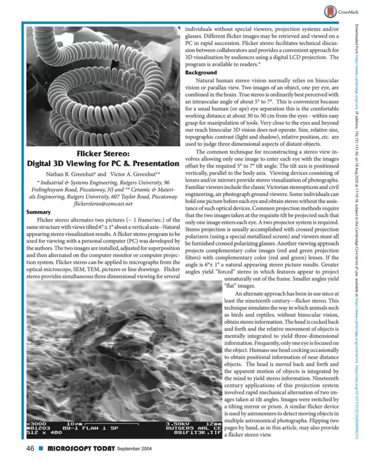
Summary Flicker stereo alternates two pictures (~ 1 frame/sec.) of the same structure with views tilted 6° ± 1° about a vertical axis—Natural appearing stereo visualization results. A flicker stereo program to be used for viewing with a personal computer (PC) was developed by the authors. The two images are installed, adjusted for superposition and then alternated on the computer monitor or computer projec- tion system. Flicker stereo can be applied to micrographs from the

  • ptical microscope, SEM, TEM, pictures or line drawings. Flicker

stereo provides simultaneous three dimensional viewing for several individuals without special viewers, projection systems and/or

  • glasses. Different flicker images may be retrieved and viewed on a

PC in rapid succession. Flicker stereo facilitates technical discus- sion between collaborators and provides a convenient approach for 3D visualization by audiences using a digital LCD projection. The program is available to readers.* Background Natural human stereo vision normally relies on binocular vision or parallax view. Two images of an object, one per eye, are combined in the brain. True stereo is ordinarily best perceived with an intraocular angle of about 5° to 7°. This is convenient because for a usual human (or ape) eye separation this is the comfortable working distance at about 30 to 50 cm from the eyes - within easy grasp for manipulation of tools. Very close to the eyes and beyond

  • ur reach binocular 3D vision does not operate. Size, relative size,

topographic contrast (light and shadow), relative position, etc. are used to judge three dimensional aspects of distant objects. The common technique for reconstructing a stereo view in- volves allowing only one image to enter each eye with the images

  • ffset by the required 5° to 7° tilt angle. The tilt axis is positioned

vertically, parallel to the body axis. Viewing devices consisting of lenses and/or mirrors provide stereo visualization of photographs. Familiar viewers include the classic Victorian stereopt icon and civil engineering, air photograph ground viewers. Some individuals can hold one picture before each eye and obtain stereo without the assis- tance of such optical devices. Common projection methods require that the two images taken at the requisite tilt be projected such that

  • nly one image enters each eye. A two projector system is required.

Stereo projection is usually accomplished with crossed projection polarizers (using a special metallized screen) and viewers must all be furnished crossed polarizing glasses. Another viewing approach projects complementary color images (red and green projection filters) with complementary color (red and green) lenses. If the angle is 6°± la a natural appearing stereo picture results. Greater angles yield "forced" stereo in which features appear to project unnaturally out of the frame. Smaller angles yield "flat" images. An alternate approach has been in use since at least the nineteenth century—flicker stereo. This technique simulates the way in which animals such as birds and reptiles, without binocular vision,

  • btain stereo information. The head is cocked back

and forth and the relative movement of objects is mentally integrated to yield three-dimensional

  • information. Frequently, only one eye is focused on

the object. Humans use head cocking occasionally to obtain positional information of near distance

  • bjects. The head is moved back and forth and

the apparent motion of objects is integrated by the mind to yield stereo information. Nineteenth century applications of this projection system involved rapid mechanical alternation of two im- ages taken at tilt angles. Images were switched by a tilting mirror or prism. A similar flicker device is used by astronomers to detect moving objects in multiple astronomical photographs. Flipping two pages by hand, as in this article, may also provide a flicker stereo view.

46

miCROJCOPY TODflT September 2004

Downloaded from https://www.cambridge.org/core. IP address: 192.151.151.66, on 18 Aug 2020 at 17:19:18, subject to the Cambridge Core terms of use, available at https://www.cambridge.org/core/terms. https://doi.org/10.1017/S1551929500056315

slide-2
SLIDE 2

Evex = NanoAnalysis

SEM Imaging 857 State Road Princeton, New Jersey 08540 (T) 609-252-9192 www.evex.com (F) 609-252-9091

SHVR/Wave Laboratory Microwave

igned for EM & lighi microscopy lissi : ssin» Minima] turn around time, same day n PlDcomml [if actual waliage No vacuum or coldspot required User friendly color touch screen controls Ideal for specimen stabilization & hardening, epitope retrieval and acceleration of decalcification & staining

TRIANGLE BIOMEDICAL SCIENCES, INC.

3014 CSOASDAILE DRIVE • DURHAM. NORTH CAROLINA 27705-2507 • USA • 919.3S4.9393 • FAX:919,354.959s • www.1riangleblomedlcal.coin

IIIICROSCOPY TODHY September 2004 • 47

Downloaded from https://www.cambridge.org/core. IP address: 192.151.151.66, on 18 Aug 2020 at 17:19:18, subject to the Cambridge Core terms of use, available at https://www.cambridge.org/core/terms. https://doi.org/10.1017/S1551929500056315

slide-3
SLIDE 3

Digital Flicker Stereo Today, flicker stereo can be accomplished conveniently on a personal computer (PC) using a Visual Basic* program developed by the authors.** The program will be provided as freeware upon request.* Two images are installed, aligned and then alternated on the computer monitor or computer projection system. A relatively natural three dimensional view of the object results. Flicker stereo can be applied to micrographs from any optical microscope, SEM,

  • r TEM, etc. A surface or transparent section may be viewed suc-
  • cessfully. Stereo images can also be reconstructed from heavy-metal

shadowed carbon replicas. Paired line drawings can also yield a stereo image. Macrographs (photographs) may also be used, as can any imaging technique that provides the required parallax views. The major utility of flicker stereo is the ability to obtain three dimensional views without special viewers, projection systems and

  • glasses. Simultaneous viewing by multiple individuals who can view

the same image is particularly convenient. This facilitates technical

  • discussion. Collaborators can point out and discuss features without

Figure 1 a & b The filament from a slide projector bulb showing (fit1 multiple helical windings of the tungsten. Helix wire width 4mm.

encountering cumbersome refocusing and interocular distance adjustment tor each user. The widespread availability ot personal computers and computer projectors makes flicker stereo an ideal way to show audiences important three dimensional information without special, expensive projection systems and glasses. Images oriented with the tilt axis rotated to the vertical are in- stalled in the program. Care should be taken to spatially match the areas viewed and provide well matched magnification, contrast, and

  • brightness. The program allows limited relative alignment of the two

images to optimize the stereoscopic impression. The flicker rate can be varied over a range because different individuals have maximum comfort and best visualization at different flicker rates. After a time using the flicker a static, single image may be worked with while still retaining the stereoscopic understanding of the image. Often SEM pictures convey misleading information because bright features appear to project out ot the image. Thus, higher sec-

  • ndary electron signal from projections, electrical nonconductors

and high atomic number material may falsely appear to be at high surface relief. Flicker stereo was found to overcome these effects very successfully and convey correct stereo aspects for both local detail and overall surfaces. The same software may also be used to assemble "film clips" as

  • ne rotates around an object or penetrates in depth. The program

appears useful for additional purposes. Studies of various applica- tions for X-ray and other SEM signals and applications are being investigated. Instructions for Viewing Flicker Stereo of Figures The stereo pair pictures in this article are printed on two suc- cessive pages. Turn the magazine sideways and rapidly lift/lower the top image. With a bit of practice a

flicker

stereo view will result. Better yet, go to the Microscopy Today webpage (www.microscopy- today.com)***, The same stereo images are available in digital flicker stereo form. You can adjust the slider on the right to get the most comfortable rate for your purposes. The images were taken digitally with uncoated samples J at low voltage (near the zero point of charge) on a ' Zeiss (LEO) Gemini 982. The stereo effect is much easier to see on a PC. • Dedication In memory of Norman Norbert Greenhut (b. 11 Feb. 1913- d. 17 April 2004), our beloved grandfather and father. A wounded World War II veteran, he made us particularly aware of the utility of flicker stereo. Endnotes

* The flicker stereo program will be provided as freeware exclusively for not-for-profit, personal use upon request to: fl ickerstereo@comcast.net * Princeton GammaTech provided a flicker stereo tool with their systems about two decades ago, but this tool was not implemented on their more recent system*. * Links to the flicker slereo program have not been set up at press time. - Ed. Figure 2 a&b Stereo images of a ballistic fragment showing an inclusion which has "popped" out of the

  • surface. Note that a hole in the ejected material becomes

apparent when flicker stereo is used.

48 • miCROfCOPYTODflY September 2004

Downloaded from https://www.cambridge.org/core. IP address: 192.151.151.66, on 18 Aug 2020 at 17:19:18, subject to the Cambridge Core terms of use, available at https://www.cambridge.org/core/terms. https://doi.org/10.1017/S1551929500056315

slide-4
SLIDE 4

STOP HASSLING WITH MULTIPLE SERVICE CONTRACTS!

START by putting all of your instruments under one service contract with MAS (regardless of make or model). Our expert EM SERVICE GROUP has the knowledge and skills to keep your instrument working at its best.

TEMS/SEMS

HITACHI TOPCON JEOL

ISI

AMRAY CAMBRIDGE

PREP EQUIPMENT SPECIAL SERVICES

VACUUM COATERS PLASMA ASHERS SPUTTER COATERS

ION MILLS

BEAM BLANKERS CUSTOM DEVICES

NEW NEW NEW

Authorized service representatives for Gatan preparation equipment and Topcon TEM'S,

Contracts and On-Demand Emergency Service at Reasonable Rates from Factory Trained Specialists.

800-421 -8451#MAS

M A Hutim S U M Suite 1 1 1 1 I U C I ; h. \< *ih I ~.n ihiu 27H *i *1<WI2MI HI FA X YI •*• ICT-5SIX ADVANCED ANALYTICAL PRODUCTS AND SERVICES

Get the power of Northern Eclipse 6.0 F R E E by ordering a Qlmaging FireWire CCD camera

When you buy a Qlmaging CCD FireWire camera directly from us at the manufacturer's suggested list price, we wilt include, for a limited time, one FREE Northern Eclipse 6.0 application of your choice. Applications such as Brightness/ Time, Time-Lapse, Image Merging, Fast Capture to Ram, and even De-convolution are available. See the On Sale page

  • f our web site for a full list of applications available with

this offer. www.empix.com E M P I X

1M 'Firewire' is a registered trademark of Apple Computer Int.

Light Guides & Custom Scintillators from

  • M. E Taylor Engineering, Inc

Light Guides for Leo/Cambridge model SEMS from $435 ITO Gold and Custom Scintillators from $89 P47 Phospor, YAG, YAP and many others Highest Quality Engineering See our web site for special offers on maintenance and recoating specials

  • M. E. Taylor Engineering, Inc.

21604 Gentry Lane Brookeville, MD 20833 Phone: (301) 774-6246

Visit us on the web: www.semsupplies.com

MICROSCOPY TODflY September 2004

49

Downloaded from https://www.cambridge.org/core. IP address: 192.151.151.66, on 18 Aug 2020 at 17:19:18, subject to the Cambridge Core terms of use, available at https://www.cambridge.org/core/terms. https://doi.org/10.1017/S1551929500056315