Finite State Machine (FSM) Consists of: CLK State register S S - - PowerPoint PPT Presentation

finite state machine fsm
SMART_READER_LITE
LIVE PREVIEW

Finite State Machine (FSM) Consists of: CLK State register S S - - PowerPoint PPT Presentation

Finite State Machine (FSM) Consists of: CLK State register S S Next Current Stores current state State State Loads next state at clock edge Combinational logic Computes the next state Computes the outputs Next


slide-1
SLIDE 1

Chapter 3 <41>

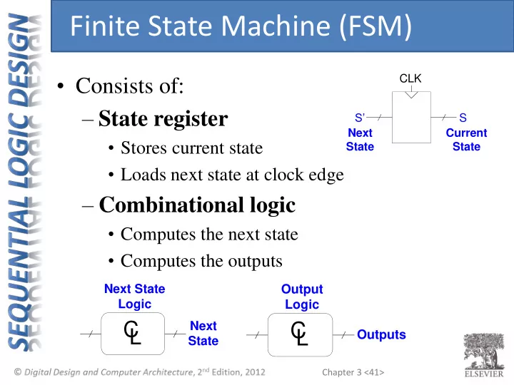
Next State Current State S’ S CLK

C L

Next State Logic Next State

C L

Output Logic Outputs

  • Consists of:

– State register

  • Stores current state
  • Loads next state at clock edge

– Combinational logic

  • Computes the next state
  • Computes the outputs

Finite State Machine (FSM)

slide-2
SLIDE 2

Chapter 3 <42>

CLK M N k k

next state logic

  • utput

logic

Moore FSM CLK M N k k

next state logic

  • utput

logic

inputs inputs

  • utputs
  • utputs

state state next state next state

Mealy FSM

  • Next state determined by current state and inputs
  • Two types of finite state machines differ in output logic:

– Moore FSM: outputs depend only on current state – Mealy FSM: outputs depend on current state and inputs

Finite State Machines (FSMs)

slide-3
SLIDE 3

Chapter 3 <43>

  • 1. Identify inputs and outputs
  • 2. Sketch state transition diagram
  • 3. Write state transition table
  • 4. Select state encodings
  • 5. Rewrite state transition table with state encodings
  • 6. Write output table
  • 7. Write Boolean equations for next state and output

logic

  • 8. Sketch the circuit schematic

FSM Design Procedure

slide-4
SLIDE 4

Chapter 3 <44>

TA LA TA LB TB TB LA LB

Academic Ave. Bravado Blvd. Dorms Fields Dining Hall Labs

  • Traffic light controller

– Traffic sensors: TA, TB (TRUE when there’s traffic) – Lights: LA, LB

FSM Example

slide-5
SLIDE 5

Chapter 3 <45>

  • 1. Identify inputs and outputs
  • 2. Sketch state transition diagram
  • 3. Write state transition table
  • 4. Select state encodings
  • 5. Rewrite state transition table with state encodings
  • 6. Write output table
  • 7. Write Boolean equations for next state and output

logic

  • 8. Sketch the circuit schematic

FSM Design Procedure

slide-6
SLIDE 6

Chapter 3 <46>

TA TB LA LB CLK Reset Traffic Light Controller

  • Inputs: CLK, Reset, TA, TB
  • Outputs: LA, LB

FSM Black Box

Note: multiple bits for output

slide-7
SLIDE 7

Chapter 3 <47>

  • 1. Identify inputs and outputs
  • 2. Sketch state transition diagram
  • 3. Write state transition table
  • 4. Select state encodings
  • 5. Rewrite state transition table with state encodings
  • 6. Write output table
  • 7. Write Boolean equations for next state and output

logic

  • 8. Sketch the circuit schematic

FSM Design Procedure

slide-8
SLIDE 8

Chapter 3 <48>

S0 LA: green LB: red Reset

  • Moore FSM: outputs labeled in each state
  • States: Circles
  • Transitions: Arcs

FSM State Transition Diagram

TA LA TA LB TB TB LA LB

Academic Ave. Bravado Blvd. Dorms Fields Dining Hall Labs

slide-9
SLIDE 9

Chapter 3 <49>

  • Moore FSM: outputs labeled in each state
  • States: Circles
  • Transitions: Arcs

FSM State Transition Diagram

S0 LA: green LB: red S1 LA: yellow LB: red S3 LA: red LB: yellow S2 LA: red LB: green TA TA TB TB Reset

TA LA TA LB TB TB LA LB

Academic Ave. Bravado Blvd. Dorms Fields Dining Hall Labs

slide-10
SLIDE 10

Chapter 3 <50>

  • 1. Identify inputs and outputs
  • 2. Sketch state transition diagram
  • 3. Write state transition table
  • 4. Select state encodings
  • 5. Rewrite state transition table with state encodings
  • 6. Write output table
  • 7. Write Boolean equations for next state and output

logic

  • 8. Sketch the circuit schematic

FSM Design Procedure

slide-11
SLIDE 11

Chapter 3 <51>

Current State Inputs Next State S TA TB S' S0 X S0 1 X S1 X X S2 X S2 X 1 S3 X X

FSM State Transition Table

S0 LA: green LB: red S1 LA: yellow LB: red S3 LA: red LB: yellow S2 LA: red LB: green TA TA TB TB Reset

slide-12
SLIDE 12

Chapter 3 <52>

Current State Inputs Next State S TA TB S' S0 X S1 S0 1 X S0 S1 X X S2 S2 X S3 S2 X 1 S2 S3 X X S0

FSM State Transition Table

S0 LA: green LB: red S1 LA: yellow LB: red S3 LA: red LB: yellow S2 LA: red LB: green TA TA TB TB Reset

slide-13
SLIDE 13

Chapter 3 <53>

  • 1. Identify inputs and outputs
  • 2. Sketch state transition diagram
  • 3. Write state transition table
  • 4. Select state encodings
  • 5. Rewrite state transition table with state

encodings

  • 6. Write output table
  • 7. Write Boolean equations for next state and output

logic

  • 8. Sketch the circuit schematic

FSM Design Procedure

slide-14
SLIDE 14

Chapter 3 <54>

Current State Inputs Next State S1 S0 TA TB S'1 S'0 X 1 X 1 X X 1 X 1 X 1 1 1 X X State Encoding S0 00 S1 01 S2 10 S3 11

FSM Encoded State Transition Table

Two bits required for 4 states

S0 LA: green LB: red S1 LA: yellow LB: red S3 LA: red LB: yellow S2 LA: red LB: green TA TA TB TB Reset

slide-15
SLIDE 15

Chapter 3 <55>

Current State Inputs Next State S1 S0 TA TB S'1 S'0 X 1 1 X 1 X X 1 1 X 1 1 1 X 1 1 1 1 X X State Encoding S0 00 S1 01 S2 10 S3 11 S'1 = S1  S0 S'0 = S1S0TA + S1S0TB

FSM Encoded State Transition Table

Two bits required for 4 states

S0 LA: green LB: red S1 LA: yellow LB: red S3 LA: red LB: yellow S2 LA: red LB: green TA TA TB TB Reset

slide-16
SLIDE 16

Chapter 3 <56>

  • 1. Identify inputs and outputs
  • 2. Sketch state transition diagram
  • 3. Write state transition table
  • 4. Select state encodings
  • 5. Rewrite state transition table with state encodings
  • 6. Write output table
  • 7. Write Boolean equations for next state and
  • utput logic
  • 8. Sketch the circuit schematic

FSM Design Procedure

slide-17
SLIDE 17

Chapter 3 <57>

Current State Outputs S1 S0 LA1 LA0 LB1 LB0 1 1 1 1 Output Encoding green 00 yellow 01 red 10

FSM Output Table

Two bits required for 3 outputs

S0 LA: green LB: red S1 LA: yellow LB: red S3 LA: red LB: yellow S2 LA: red LB: green TA TA TB TB Reset

slide-18
SLIDE 18

Chapter 3 <58>

Current State Outputs S1 S0 LA1 LA0 LB1 LB0 1 1 1 1 1 1 1 1 1 1 Output Encoding green 00 yellow 01 red 10 LA1 = S1 LA0 = S1S0 LB1 = S1 LB0 = S1S0

FSM Output Table

Two bits required for 3 outputs

S0 LA: green LB: red S1 LA: yellow LB: red S3 LA: red LB: yellow S2 LA: red LB: green TA TA TB TB Reset

slide-19
SLIDE 19

Chapter 3 <59>

  • 1. Identify inputs and outputs
  • 2. Sketch state transition diagram
  • 3. Write state transition table
  • 4. Select state encodings
  • 5. Rewrite state transition table with state encodings
  • 6. Write output table
  • 7. Write Boolean equations for next state and output

logic

  • 8. Sketch the circuit schematic

FSM Design Procedure

slide-20
SLIDE 20

Chapter 3 <60>

S1 S0 S'1 S'0 CLK

state register

Reset r

FSM Schematic: State Register

S'1 = S1  S0 S'0 = S1S0TA + S1S0TB LA1 = S1 LB1 = S1 LA0 = S1S0 LB0 = S1S0

slide-21
SLIDE 21

Chapter 3 <61>

S1 S0 S'1 S'0 CLK

next state logic state register

Reset TA TB

inputs

S1 S0 r

FSM Schematic: Next State Logic

S'1 = S1  S0 S'0 = S1S0TA + S1S0TB

slide-22
SLIDE 22

Chapter 3 <62>

S1 S0 S'1 S'0 CLK

next state logic

  • utput logic

state register

Reset LA1 LB1 LB0 LA0 TA TB

inputs

  • utputs

S1 S0 r

FSM Schematic: Output Logic

LA1 = S1 LB1 = S1 LA0 = S1S0 LB0 = S1S0

slide-23
SLIDE 23

Chapter 3 <63>

CLK Reset TA TB S'1:0 S1:0 LA1:0 LB1:0 Cycle 1 Cycle 2 Cycle 3 Cycle 4 Cycle 5 Cycle 6 Cycle 7 Cycle 8 Cycle 9 Cycle 10 S1 (01) S2 (10) S3 (11) S0 (00) t (sec) ?? ?? S0 (00) S0 (00) S1 (01) S2 (10) S3 (11) S1 (01) ?? ??

5 10 15 20 25 30 35 40 45 Green (00) Red (10)

S0 (00)

Yellow (01) Red (10) Green (00) Green (00) Red (10) Yellow (01) S0 LA: green LB: red S1 LA: yellow LB: red S3 LA: red LB: yellow S2 LA: red LB: green TA TA TB TB Reset

FSM Timing Diagram

slide-24
SLIDE 24

Chapter 3 <64>

  • Binary encoding:

– i.e., for four states, 00, 01, 10, 11

  • One-hot encoding

– One state bit per state – Only one state bit HIGH at once – i.e., for 4 states, 0001, 0010, 0100, 1000 – Requires more flip-flops – Often next state and output logic is simpler

FSM State Encoding

slide-25
SLIDE 25

Chapter 3 <65>

  • 1. Identify inputs and outputs
  • 2. Sketch state transition diagram
  • 3. Write state transition table
  • 4. Select state encodings
  • 5. Rewrite state transition table with state encodings
  • 6. Write output table
  • 7. Write Boolean equations for next state and output

logic

  • 8. Sketch the circuit schematic

FSM Design Procedure