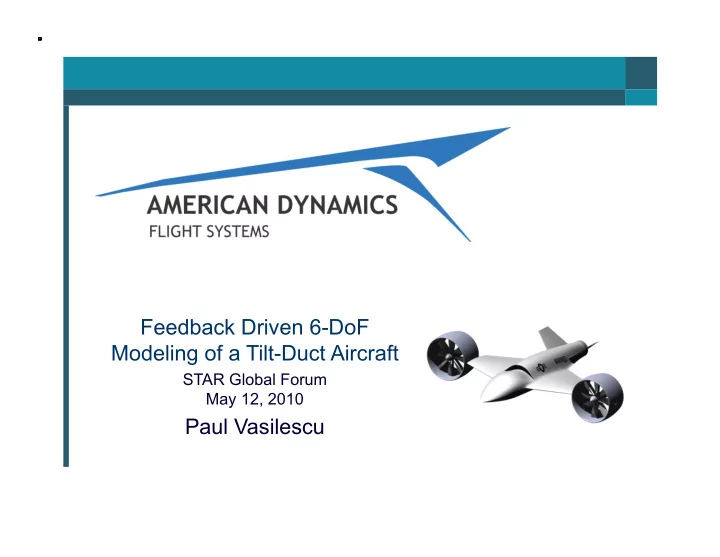

Feedback Driven 6-DoF Modeling of a Tilt-Duct Aircraft STAR Global Forum May 12, 2010 Paul Vasilescu
AD-150 High Speed VTOL UAV - Designed around USMC Tier III requirements (Now Group IV) - VTOL from air capable ships - Exceed 200 kts airspeed Length 14.5 ft Wing Span 17.5 ft Height 4.75 ft Takeoff Weight 2,200 lbs - 2,800 lbs Max Payload 500 lbs - 1,000 lbs Max Speed 300 kts Max Range 736 Nmi 2
Our Business Model Create a multi-mission, economical, high-speed VTOL UAV to fill a market void Team with industry leaders for payload, subsystem and contracting support Secure production contracts for airframes and lift and propulsion systems Flight Control Ruddervator Actuators HTAL Designed & Nacelle Vectoring Manufactured by Nozzle ADFS in Jessup, MD Turboshaft HTAL Fan Powerplant Designed by ADFS, Drive Manufactured by Flaperon System ADFS and/or Power Main Landing Gear Subcontractors Management Mission Designed & Payload HTAL Airframe Avionics Manufactured by System Navigation Subcontractors Nose Landing Gear & Control
AD-150 Development Timeline 2006 2007 2008 2009 2010 2011
Tilt-Duct VTOL ~ Key Challenges Transition between hover and forward flight Dynamic conditions Large pitching moments Potential duct stall Low control authority Static / steady state limitations Transient 6-DoF solution A full understanding of flight conditions experienced in transition requires a comprehensive transient simulation
AD-150 6-DoF CFD Model Create a robust 6-DoF CFD simulation to accurately model transition between hover and forward flight Support changes in geometric configuration between time steps Duct angle relative to the fuselage Angle-of-Attack Support basic autopilot user code Run on top of the simulation Read inertial data at each time step Implement geometric and power changes Must be accurate but also feasible Split the propulsion model from the aircraft model Verify data using multiple CFD methods Validate CFD models with experimental tests 6 Use is limited to Proprietary Restriction on the cover 6
Steady State Propulsion Model Star-CCM+ steady state segregated flow model with moving reference frame Automated workflow solved every case in the test matrix Test matrix includes variations Duct Angle Feestream Velocity Fan RPM Measured data includes 6 Component Forces and Moments Fan Torque Airflow Velocity (above and below fan disk) Data was fit to mathematical curves to enable integration into any flight condition modeled by the unsteady model 7 Use is limited to Proprietary Restriction on the cover 7
Aircraft 6-DoF Model Star-CCM+ unsteady 6-DoF Nacelles modeled in cylindrical volumes Enables rotation of the ducts without remeshing In-place interfaces used between all volumes Boundary conditions replace rotating fans Computed dynamically for each time step based on data from the propulsion system CFD Validated by comparing 6 component forces and moments of both models Angle-of-Attack changes are achieved by rotating all volumes about the aircraft’s CG Basic autopilot code sets power, duct angle, and angle-of-attack at each time step Initial runs enabled translation in all directions and rotation in the yaw axis 8 Use is limited to Proprietary Restriction on the cover 8
Feedback Driven CFD 6-DoF Workflow 9 Use is limited to Proprietary Restriction on the cover 9
AD-150 6-DoF Initial Cases 10 Use is limited to Proprietary Restriction on the cover 10
AD-150 CFD 6-DoF Team Qlogic NETrack Development Center (NDC) Test drive HPC systems 16 Dell PowerEdge R610 Compute Nodes w/ Qlogic TrueScale InfiniBand 128 Total CPU Cores and 384 GB RAM Performance Improvement Reduced 3000 hours of compute time to 48 hours for the stead state propulsion simulation test matrix Reduced 93.4 hours of compute time per second of flight time of the unsteady / transient aircraft simulation to 2.4 hours of compute time per second of flight time 11 Use is limited to Proprietary Restriction on the cover 11
Experimental Validation Aircraft Wind Tunnel Test Built and tested a 1/3 scale model of the AD-150 aircraft Tests conducted at the Glen L. Martin Wind Tunnel in Q1 2009 Performed static and dynamic tests over a wide range of combinations of angle of attack, sideslip and forward speed Confirmed CFD performance data and validated airframe design Funding provided by the state of Maryland through the Maryland Industrial Partnerships program (MIPS) “The American Dynamics Flight Systems team came to the wind tunnel test with a more complete set of CFD results directly comparable to the tunnel conditions than any other group we have worked with up to now.” -- Dr. Jewel Barlow, Director of the Glenn L. Martin Wind Tunnel
Experimental Validation Propulsion Wind Tunnel Test Build an test a scaled AD-150 propulsion system in a wind tunnel Simulate conditions experienced during transition between hover and forward flight Test will be conducted and the UMD Glenn L. Martin Wind Tests will include variances in freestream velocity, fan velocity, and duct angle Measurements will be taken and compared to equivalent data taken from the computational models Funding provided by the state of Maryland through the Maryland Industrial Partnerships program (MIPS)
Experimental Validation Propulsion Static Test Build and integrate a fully instrumented test rig for the AD-150 lift and propulsion system Tests to be conducted at Aberdeen Proving Grounds later this year Mechanically validate propulsion and drive components Confirm CFD performance data for hover in ground effect (HIGE) and hover out of ground effect (HOGE) Provide a comprehensive data set of system performance and reliability Funding provided by the state of Maryland through the Maryland Technology Transfer Fund (MTTF) program
Next Steps Movable control surfaces Stability augmentation code Turboshaft engine code Replace AP code with software and hardware interfaces to a physical autopilot Create a full CFD based hardware-in- the-loop (HIL) simulator 15 Use is limited to Proprietary Restriction on the cover 15
Thank you
Recommend
More recommend