FEC403EN Extinguishing Control Panel FEC403EN Extinguishing panel - - PowerPoint PPT Presentation
FEC403EN Extinguishing Control Panel FEC403EN Extinguishing panel Table of contents Panel Features Panel Hardware System Description 2 / GE / FEC403EN Extinguishing panel Table of contents The FEC403EN conventional extinguishing
2 / GE /
FEC403EN Extinguishing panel
Table of contents
- Panel Features
- Panel Hardware
- System Description
3 / GE /
FEC403EN Extinguishing panel
Table of contents
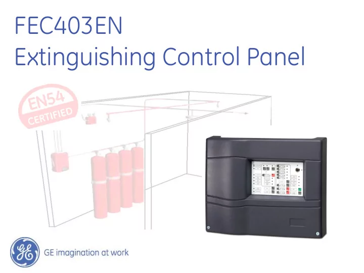
The FEC403EN conventional extinguishing control panel is EN54 approved for single area applications. Very powerful and cost-effective, it is extremely easy to install and use due to its advanced design. The panel has 1 double-knock (coincidence) extinguishing area consisting of two fire zones with 1 free fire detection zone to protect the panel.
4 / GE /
FEC403EN Extinguishing panel
Standard Features
- EN54-2, EN54-4 and EN12094-1 approved; Class A: -5°C to +40°C
- 3 Zones
1 Extinguishing area with 2 detection zones 1 Standard fire zone
- MCP Start, hold and abort options
- Optical panel control for warning, evacuation and release indications
- Extinguishing agent release control (Solenoid/pyrotechnic selectable)
- All inputs and outputs supervised
- Common outputs with potential free relays
- Optional additional relay and supervised outputs
- One-man test capability
5 / GE /
Extinguishing Options
Options supported
- Manual or automatic mode
- Delay to gas release
- Release state indication from gas flow switch or actuator
- Hold mode: French (restart delay) or UK (keep delay)
- Door monitoring
- Output to fire routing
- Output to fault routing
- Clean-me compliant
6 / GE /
Extinguishing Options
Options not supported
- Spare bank cylinders (multiple bank discharge)
- Low pressure CO2
- Mechanically selection of flooding zone
7 / GE /
FEC403EN Extinguishing panel
Table of contents
- Panel Features
- Panel Hardware
- System Description
8 / GE /
FEC403EN Extinguishing Control Panel
Main component location
- 1. Power supply
- 2. Earth stud
- 3. Zone, fire detection and
extinguishing system input/output connectors
- 4. Configuration DIP switches
- 5. Control panel keypad
- 6. Master relay module connector
- 7. Keypad to PCB connector
- 8. Batteries
- 9. 230 VAC supply connector and
fuse
9 / GE /
FEC403EN Extinguishing Control Panel
Supervised inputs and outputs overview (1)
- Pyrotechnic and Solenoid outputs (500 mA)
- Fire brigade output (250 mA)
- 3 x Illuminated warning sign outputs (450 mA each)
Gas released Evacuate Warning
- 2 x Sounder outputs (250 mA each)
- 2 x Relay outputs (1 A)
Common fault (with return) Common alarm
- 24 VDC Aux resetable output (100 mA)
- 24 VDC Standard output (1.3A)
10 / GE /
FEC403EN Extinguishing Control Panel
Supervised inputs and outputs overview (2)
- 2 x Communication outputs
Serial Communications (for RB/SB404) RS485 Communications (for future use)
- Door monitor input
- Gas flow switch input
- Pressure switch input
- Auto/Manual mode input
- 3 x Extinguishing control MCPs
Abort extinguishing Hold extinguishing Start extinguishing
- 3 x Fire zone inputs (20 detectors or 32 MCPs)
11 / GE /
FEC403EN Extinguishing Control Panel
All controls and indications on a standard user interface
12 / GE /
FEC403EN Extinguishing Control Panel
Common Indications (Block 1)
1. Fire LEDs (general / zone) 2. Fault LEDs (general / zone) 3. Maintenance LED 4. Fault return LED 5. Supply fault LED 6. System fault LED 7. Out of service LED 8. Supply on LED
13 / GE /
FEC403EN Extinguishing Control Panel
Indications (Block 2)
- 10. Test LED
- 11. Manual mode LED
- 12. Start MCP fault LED
- 13. Released LED
- 14. Extinguishing activated LED
- 15. Extinguishing fault / disable LED
14 / GE /
FEC403EN Extinguishing Control Panel
Indications (Block 3)
- 16. Hold MCP LEDs (Active / Fault)
- 17. Abort MCP LEDs (Active / Fault)
- 18. Gas pressure LEDs (Active / Fault)
- 19. Gas flow LEDs (Active / Fault)
- 20. Door monitor LEDs (Active / Fault)
- 21. Fire Brigade delay LED
- 22. Fire Brigade start LEDs (Active / Fault)
- 23. Sounder 1 stop LEDs (Active / Fault)
- 24. Sounder 2 stop LEDs (Active / Fault)
15 / GE /
FEC403EN Extinguishing Control Panel
- 25. Silence buzzer LED
- 26. Reset LED
- 27. Auxiliary disabled LED
- 28. Warning sign fault LED
- 29. Evacuate sign fault LED
- 30. Released sign fault LED
Indications (Block 4)
16 / GE /
FEC403EN Extinguishing Control Panel
Front panel controls
- A. Zone buttons (Z1, Z2, Z3)
- B. Disable extinguishing button
- C. Test button
- D. Disable button (general)
- E. Sounder 2 stop button
- F. Sounder 1 stop button
- G. Fire brigade start button
- H. Fire brigade delay button
J. Silence Buzzer button
- K. Reset button
- L. Access key (level 1 / level 2)
17 / GE /
FEC403EN Extinguishing panel
Table of contents
- Panel Features
- Panel Hardware
- System Description
18 / GE /
FEC403EN Extinguishing panel
System Compatibility Edwards Aritech Kilsen
Full GE Security system compatibility with all conventional devices
Ziton
19 / GE /
FEC403EN Extinguishing panel
System Features
- Supports the full line of EN54 approved sensors in the GE Security,
Aritech, Edwards, Kilsen and Ziton brands
- Supports maintenance (CleanMe™) indications from the Aritech
700 Series devices
- Supports output expansions, both supervised and unsupervised
- Support active-end-of-line zones with head-out supervision