
SLIDE 1
1 IMAPS/ACerS 12th CICMT, Denver, 19-21.4.2016
Thomas Maeder, Caroline Jacq, Stefane Caseiro and Peter Ryser
École Polytechnique Fédérale de Lausanne (EPFL), Switzerland
Assessment of TFRs for piezoresistive sensors
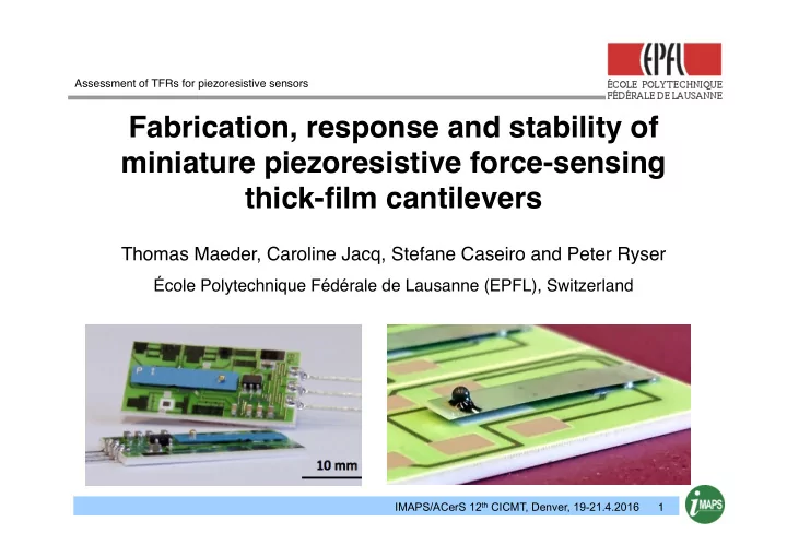
Fabrication, response and stability of miniature piezoresistive - - PowerPoint PPT Presentation
Assessment of TFRs for piezoresistive sensors Fabrication, response and stability of miniature piezoresistive force-sensing thick-film cantilevers Thomas Maeder, Caroline Jacq, Stefane Caseiro and Peter Ryser cole Polytechnique Fdrale de
1 IMAPS/ACerS 12th CICMT, Denver, 19-21.4.2016
Assessment of TFRs for piezoresistive sensors
2 IMAPS/ACerS 12th CICMT, Denver, 19-21.4.2016
Outline
3 IMAPS/ACerS 12th CICMT, Denver, 19-21.4.2016
Outline
4 IMAPS/ACerS 12th CICMT, Denver, 19-21.4.2016
n Typical elements
n Sensing bridge n Offset trim n TCO trim n Differential amplifier
n Typical values (±)
n Offset ~30 mV/V n Response ~2-3 mV/V n TCO ~1 µV/V/K
n For 0.1% F.S.:
n Offset reduction ~10'000× n Stability (bridge) ~2-3 ppm
1 - Introduction
5 IMAPS/ACerS 12th CICMT, Denver, 19-21.4.2016
n Piezoresistive bridge n Thick-film resistors n Gauge factor KL ~12
6 IMAPS/ACerS 12th CICMT, Denver, 19-21.4.2016
n L : for stress n d+ : positive signal (avg.) n d– : positive signal (avg.) n d : signal (overall) n b : cantilever width n h : cantilever thickness
2 d + − d –
7 IMAPS/ACerS 12th CICMT, Denver, 19-21.4.2016
1 - Introduction
n Full active bridge n Little thermal drift
n Double-side, complex
n More difficult resistor
n Layers on top side n Sensitive to horizontal
8 IMAPS/ACerS 12th CICMT, Denver, 19-21.4.2016
1 - Introduction
n Single-side, simple n Good resistor matching
n Blank top side n Little thermal drift
n Half bridge, less
n Sensitive to horizontal
9 IMAPS/ACerS 12th CICMT, Denver, 19-21.4.2016
1 - Introduction
n Single-side, simple n Good resistor matching
n Blank top side n Horizontal force
n Half bridge, sensitivity
n Buried conductors?
10 IMAPS/ACerS 12th CICMT, Denver, 19-21.4.2016
1 - Introduction
n Very good performance for ZrO2:Y (YSZ) & ZTA n Glassy (Al2O3 96% & LTCC) : poorer
11 IMAPS/ACerS 12th CICMT, Denver, 19-21.4.2016
1 - Introduction
n Strong degradation of high-strength substrates (ZrO2 & ZTA) n ZrO2 & ZTA better with single-side cantilevers (blank top side)
12 IMAPS/ACerS 12th CICMT, Denver, 19-21.4.2016
1 - Introduction
n Strong degradation of high-strength substrates (ZrO2 & ZTA) n ZrO2 & ZTA better with single-side cantilevers (blank top side)
13 IMAPS/ACerS 12th CICMT, Denver, 19-21.4.2016
1 - Introduction
n Single-side n Good resistor matching n Higher signal by structuration
n Concentration of compression n In practice ~2x
n Horizontal force compensation
n LTCC process critical for thin,
n Resistor compatibility n Drift???
14 IMAPS/ACerS 12th CICMT, Denver, 19-21.4.2016
1 - Introduction
n Moderate, consistent
n No apparent drift
15 IMAPS/ACerS 12th CICMT, Denver, 19-21.4.2016
1 - Introduction
n Abnormally high
n Strong variations
n Significant drift
16 IMAPS/ACerS 12th CICMT, Denver, 19-21.4.2016
1 - Introduction
n Ferroelasticity n Problematic for elastic substrate…
17 IMAPS/ACerS 12th CICMT, Denver, 19-21.4.2016
Outline
18 IMAPS/ACerS 12th CICMT, Denver, 19-21.4.2016
1 - Introduction
n All pre-fired n Not structured, same layout
19 IMAPS/ACerS 12th CICMT, Denver, 19-21.4.2016
20 IMAPS/ACerS 12th CICMT, Denver, 19-21.4.2016
n Resistors (DP 2041) on dielectric:
n 3YSZ : ESL 4931 (for steel -> CTE ~ YSZ) n Others : ESL 4913 + 4917 (low CTE)
n 3YSZ : 45 µm critical, 90 µm OK n Al2O3 / ZTA : OK down to 150 µm (ZTA recommended) n LTCC : flatness critical (DP951 ≳ HL2000 > CT700)
21 IMAPS/ACerS 12th CICMT, Denver, 19-21.4.2016
Outline
22 IMAPS/ACerS 12th CICMT, Denver, 19-21.4.2016
n Very low heat conductance (45 µm thick, k ~ 2-3 W/m/K) n Thermal drift max ~1% (for 2'000 ppm F.S.)
23 IMAPS/ACerS 12th CICMT, Denver, 19-21.4.2016
n Same material, 2x thickness n ½ thermal drift
24 IMAPS/ACerS 12th CICMT, Denver, 19-21.4.2016
n Very low thermal drift even for thinnest Al2O3
25 IMAPS/ACerS 12th CICMT, Denver, 19-21.4.2016
Outline
26 IMAPS/ACerS 12th CICMT, Denver, 19-21.4.2016
n High signal level, consistent n No visible drift (<±5 ppm) n Linear signal, ~43 ppm/mN
27 IMAPS/ACerS 12th CICMT, Denver, 19-21.4.2016
n High signal level, quite consistent n Linear signal, ~20 ppm/mN n Slight drift?
28 IMAPS/ACerS 12th CICMT, Denver, 19-21.4.2016
n High signal level, quite consistent n Linear signal, ~20 ppm/mN n Slight drift?
29 IMAPS/ACerS 12th CICMT, Denver, 19-21.4.2016
n High signal level, quite consistent n Linear signal, ~20 ppm/mN n Slight drift?
30 IMAPS/ACerS 12th CICMT, Denver, 19-21.4.2016
n Apparent drift similar for both layouts
31 IMAPS/ACerS 12th CICMT, Denver, 19-21.4.2016
n Expected magnitude vs 90 µm YSZ (B) & 400 µm Al2O3 (C) n Very clean signal
32 IMAPS/ACerS 12th CICMT, Denver, 19-21.4.2016
n Expected magnitude vs 90 µm YSZ (B) & 400 µm Al2O3 (C) n Very clean signal
33 IMAPS/ACerS 12th CICMT, Denver, 19-21.4.2016
n High signal, large variations n Visible zero drift (not anelastic) – damage ? n No apparent dependence on layout
34 IMAPS/ACerS 12th CICMT, Denver, 19-21.4.2016
n High signal, large variations n Visible zero drift (not anelastic) – damage ? n No apparent dependence on layout
35 IMAPS/ACerS 12th CICMT, Denver, 19-21.4.2016
n Thicker: mostly similar behaviour n Some "clean" samples
36 IMAPS/ACerS 12th CICMT, Denver, 19-21.4.2016
n Thicker: mostly similar behaviour n Some "clean" samples
37 IMAPS/ACerS 12th CICMT, Denver, 19-21.4.2016
n Different LTCC : similar behaviour
38 IMAPS/ACerS 12th CICMT, Denver, 19-21.4.2016
n Different LTCC : similar behaviour
39 IMAPS/ACerS 12th CICMT, Denver, 19-21.4.2016
n Different LTCC : similar behaviour
40 IMAPS/ACerS 12th CICMT, Denver, 19-21.4.2016
n Increase of drift with apparent signal -> anomaleous
41 IMAPS/ACerS 12th CICMT, Denver, 19-21.4.2016
Outline
42 IMAPS/ACerS 12th CICMT, Denver, 19-21.4.2016
n Thin cantilevers on many substrates, including LTCC n Same manufacturing process:
n Post-fired, single-side n Two-layer, piezoresistors on thick-film dielectric n Resistors allowed above buried tracks (variant 3) or not (variant 2)
n Results:
n Al2O3 / ZTA : clean signal, thermal drift not a problem n 3YSZ : possibly slight anelastic drift & thermal effects due to very low
n LTCC : signal mostly unstable (some clean samples)
n Cause ? Low thermal expansion ?
43 IMAPS/ACerS 12th CICMT, Denver, 19-21.4.2016
n Elucidate drift mechanism on LTCC
n Perform progressive loading tests n Check for resistor damage n Try on LTCC with high CTE – should avoid instabilities
n Extended analysis of new design
n Performance & economics vs existing cantilever n Sensitivity to side loads n Lowest practical force ranges (deflection, manufacturing…)
44 IMAPS/ACerS 12th CICMT, Denver, 19-21.4.2016