
SLIDE 1
Experimental study of droplet characteristics in dropwise condensation along the axial length of a long vertical tube
Taeseok Kima, Sung Joong Kima,b*
a Department of Nuclear Engineering, Hanyang University, 222 Wangsimni-ro, Seongdong-gu, Seoul 04763 Republic
- f Korea
b Institute of Nano Science & Technology, Hanyang University, 222 Wangsimni-ro, Seongdong-gu, Seoul 04763
Republic of Korea
*Corresponding author: sungjkim@hanyang.ac.kr
- 1. Introduction
The dropwise condensation has been a considerable interest to many researchers due to higher heat transfer performance than filmwise condensation. Several studies have investigated the heat transfer mechanism
- f dropwise condensation [1-3] and droplet growth
behavior on the micro/nano modified surface [4-6]. These studies observed the detailed mechanism by using experimental facilities adopting mostly horizontal tubes or short vertical plates. However, many industrial facilities adopting condensation heat transfer such as passive containment cooling system (PCCS) and emergency core-makeup tank (ECT) applicable for the nuclear power plant systems employ long vertical tubes [7]. In the long vertical tube, the condensate flows down along the surface and it sweeps
- ut other residual droplets. Thus, it may cause unique
condensation characteristics between upside and downside of the vertical surface. Surprisingly, however, no studies so far identified the characteristic transition of droplet behavior with distance from the beginning of condensation in a vertical tube. Therefore, the goal of this study is to observe condensate droplet
- n the upside and downside of the vertical tube.
- 2. Experimental method
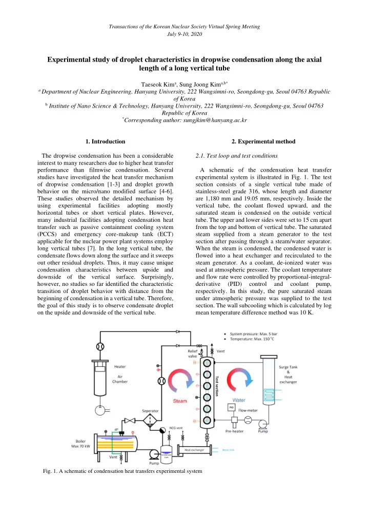
2.1. Test loop and test conditions A schematic of the condensation heat transfer experimental system is illustrated in Fig. 1. The test section consists of a single vertical tube made of stainless-steel grade 316, whose length and diameter are 1,180 mm and 19.05 mm, respectively. Inside the vertical tube, the coolant flowed upward, and the saturated steam is condensed on the outside vertical
- tube. The upper and lower sides were set to 15 cm apart
from the top and bottom of vertical tube. The saturated steam supplied from a steam generator to the test section after passing through a steam/water separator. When the steam is condensed, the condensed water is flowed into a heat exchanger and recirculated to the steam generator. As a coolant, de-ionized water was used at atmospheric pressure. The coolant temperature and flow rate were controlled by proportional-integral- derivative (PID) control and coolant pump,
- respectively. In this study, the pure saturated steam
under atmospheric pressure was supplied to the test
- section. The wall subcooling which is calculated by log
mean temperature difference method was 10 K.
- Fig. 1. A schematic of condensation heat transfers experimental system