
SLIDE 1
William Sandqvist william@kth.se
Energy transfer with a resistor
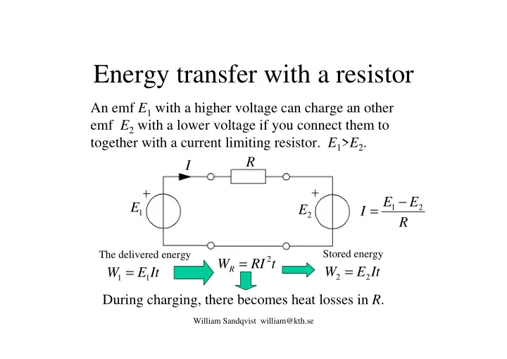
An emf E1 with a higher voltage can charge an other emf E2 with a lower voltage if you connect them to together with a current limiting resistor. E1>E2.
1
E
2
E R E E I
2 1 −
= During charging, there becomes heat losses in R. It E W
1 1 =
It E W
2 2 =
t RI WR
2
=
The delivered energy Stored energy