Embedded Systems Programming Quark SOC and Galileo (Module 7) - - PowerPoint PPT Presentation

embedded systems programming
SMART_READER_LITE
LIVE PREVIEW

Embedded Systems Programming Quark SOC and Galileo (Module 7) - - PowerPoint PPT Presentation

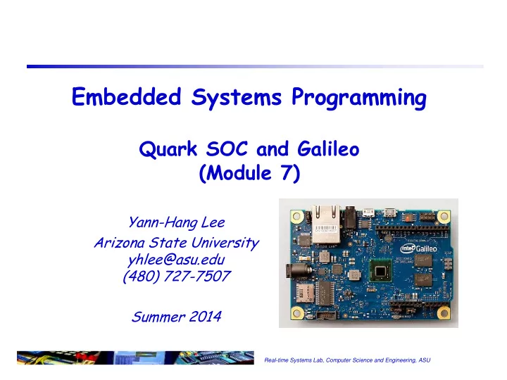
Embedded Systems Programming Quark SOC and Galileo (Module 7) Yann-Hang Lee Arizona State University yhlee@asu.edu (480) 727-7507 Summer 2014 Real-time Systems Lab, Computer Science and Engineering, ASU Current Processor Design


slide-1
SLIDE 1

Real-time Systems Lab, Computer Science and Engineering, ASU

Yann-Hang Lee Arizona State University yhlee@asu.edu (480) 727-7507 Summer 2014

Embedded Systems Programming

Quark SOC and Galileo (Module 7)

slide-2
SLIDE 2

Real-time Systems Lab, Computer Science and Engineering, ASU

Current Processor Design

 Moore’s law continues to hold true, transistor counts doubling

every 18 months

 But can no longer rely upon increasing clock rates and instruction-

level parallelism to meet computing performance demands

 Semiconductor device fabrication process

 65 nm – 2006, 45 nm – 2008, 32 nm – 2010, and 22 nm – 2012

 How to best exploit ever-increasing on-chip transistor counts?

 Multi- & many-core (MC) devices are new technology wave  exploiting explicit parallelism in the new devices

 Size and Power constraints

1

slide-3
SLIDE 3

Real-time Systems Lab, Computer Science and Engineering, ASU

Intel Processors

 X86 32/64 architecture

 486 – first pipelined x86 design  Pentium – the first x86 superscalar CPU

 Processors for

 Server (Xeon), desktop (Core i3/i5/i7), mobile (Core i3/i5/i7), and

embedded (Atom)

 All of them support hypervisor (VM)

 Differences

 CPUs, memory, and interconnection bandwidth  reliability (quality of dies) and form factor  power and thermal requirements

 Uses available clock cycles and power, not to push up

higher clock speeds and energy needs

2

slide-4
SLIDE 4

Real-time Systems Lab, Computer Science and Engineering, ASU

Galileo Board

 400MHz Quark SoC  256MB DDR3  Ethernet  USB Host Port  MicroSD Support  I2C, SPI Support  PCI Express Mini Cards  Serial Connectivity  GPIO  Linux on Board

Source: http://www.intel.com/content/www/us/en/intelligent-systems/galileo/galileo-overview.html

3

slide-5
SLIDE 5

Real-time Systems Lab, Computer Science and Engineering, ASU

Intel Quark SoC X1000.

 SOC –

 CPU core (x86)  cache, internal memory (flash, SRAM)  IO interfaces and external buses  interconnection or switches  misc (clock, JTAG)

 Chip size, power and pins

 32nm process in 1st Quark  one-fifth the size and

  • ne-tenth the power of

low-end Atom chip

 393 solder balls on 15mm2  5 power rails (3.3V, 1.8V,

1.5V, 1.05V, 1.0V)

4

slide-6
SLIDE 6

Real-time Systems Lab, Computer Science and Engineering, ASU

Quark Core Internal Architecture

 32-bit RISC integer

core

 Single cycle execution  Instruction pipelining  Floating-point unit  Cache with cache

consistency support (16-Kbyte for both data and instructions)

 Memory management

unit

5

slide-7
SLIDE 7

Real-time Systems Lab, Computer Science and Engineering, ASU

486 Pipeline

6

slide-8
SLIDE 8

Real-time Systems Lab, Computer Science and Engineering, ASU

 Example: High Speed UART Interface, SIU1_RDX SIU1_TXD  Six different power states

 S0 – the system is completely powered ON and fully operational  S5 – the system is completely powered OFF  S1, S2, S3 and S4 – sleeping states, the system appears OFF because

  • f low power consumption and retains enough of the hardware context

to return to the working state

 In Galileo schematics

Pins in Quark

Default Buffer State Signal Name Dir Term Power Type S4/S5 S3 Reset Enter S0 SIU0_RXD I 20k(H) 3.3V CMOS3.3 Off Off Pull-up Pull-up SIU0_TXD O

  • 3.3V CMOS3.3

Off Off VOH VOH

7

slide-9
SLIDE 9

Real-time Systems Lab, Computer Science and Engineering, ASU

IO Expander and GPIO Multiplexing

 CY8C9540A – I2C interfaced expander

 with 40 I/O data pins (ports 0-5) independently configurable as

inputs, outputs, bi-directional input/outputs, or PWM outputs

 To configure a pin

 an I2C control message to the chip which

includes a register address

8