effect of stiffness eccentricity on seismic response of
play

Effect of Stiffness Eccentricity on Seismic Response of Simple - PDF document

Transactions of the Korean Nuclear Society Virtual Spring Meeting July 9-10, 2020 Effect of Stiffness Eccentricity on Seismic Response of Simple Irregular Structures Juseung Ryu, Jisu Kim, Taemyung Shin* Dept. of Aeronautical & Mechanical


  1. Transactions of the Korean Nuclear Society Virtual Spring Meeting July 9-10, 2020 Effect of Stiffness Eccentricity on Seismic Response of Simple Irregular Structures Juseung Ryu, Jisu Kim, Taemyung Shin* Dept. of Aeronautical & Mechanical Design Engr., Korea Nat. University of Transportation. * Corresponding author: tmshin@ut.ac.kr 1. Introduction simulate concentric or eccentric stiffness of the structures. Recently, some researches have shown that the contribution of the rotational seismic response is a little higher than expected in case of strong motion beyond design basis earthquake (BDBE) for some typical structures with irregular shapes and dynamic characteristics. The design requirement considering inherent and accidental torsional moment resulting from mass or stiffness eccentricity in applicable codes like ASCE 7-10, ASCE 4-16, FEMA460, and etc. has been well defined and accepted enough conservative for the seismic design of most structures. However, there are a couple of special cases that the requirement may not be (a) Test model (b) Analysis model sufficient in predicting rotational effect on structural Fig. 1. Shape of regular structures. seismic response in strong earthquakes. For example, they propose the rotational component of ground motion can significantly affect the rocking response of fixed- Table I: Material properties of test model based high rise structures, the torsional response of Top Plate Column irregular structures or fluid tanks, the rocking and Size (mm) 180×250×5.8 34×270×1.1 torsional response of base-isolated structures, and etc. Density ( 𝑙𝑕 / 𝑛 3 ) 7467 7728 [1,2] E ( 𝑄𝑏 ) 2e11 2e11 In this study, one of the technical investigations has Poisson’s ratio 0.31 0.31 been attempted while seismic base-isolation technology is studied to improve seismic performance of nuclear To distinguish the analysis models with different power plant against BDBE. That is an analysis of a number of support columns, models are named as four- simple structure with eccentric stiffness to get some basic digit figures by the exact number of columns located at idea of dynamic trend of irregular structures and each corner counterclockwise. For example, the regular contribution of rotational mode to translational response. model using one support equally at all 4 corners is called For the purpose, a simple test structure and simulated as 1111, and the model using two supports equally at 4 analytical model are prepared with some varied corners is 2222. Otherwise, 2111 is the irregular model combination of support columns. And mode shapes and with double supports at 1 corner and single support at 3 seismic responses of the analysis model are reviewed and corners. And 1222 is the irregular model with single compared between regular and irregular structures after support at 1 corner and double supports at 3 corners. In adjusting the fundamental frequency of the model similar addition, for comparison of structural regularity and to that of the test. The results are to be referenced to irregularity effects on the seismic responses, the regular check the seismic torsional and rocking response models having equivalent shear stiffness to 2111 and characteristics of base-isolated structures. 1222 are designed, by adjusting the bracket thickness equally at 4 corners, and named as 2111EQ and 1222EQ, 2. Schematics of structural model
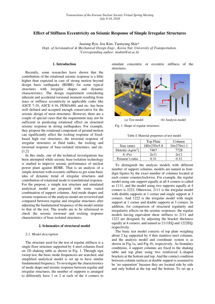
 respectively. The basic test model consists of top plate weighing 2.1. Model description about 2 kg supported by 4 thin stainless-steel columns, and the analysis model and coordinate system is as The structure used for the test of regular stiffness is a shown in Fig.1a, and Fig.1b, respectively. As boundary single floor structure supported by 4 steel columns fixed conditions, 4 support columns are fixed to the shaking on 1D shaking table as shown in Fig. 1. Through sign table and top plate using two reinforced L-shaped sweep test, the basic mode frequencies are searched, and brackets at the bottom and top. And the contact condition simplified analytical model is set up to have similar between column surfaces at double support is assumed to fundamental frequency. To investigate the characteristics be ‘no separation’ because they are located side by side of mode shape and seismic response between regular and and only bolted at the top and the bottom. To set up a irregular structures, the number of supports is arranged to differently have 1 or 2 at each of the 4 corners to

  2. Transactions of the Korean Nuclear Society Virtual Spring Meeting July 9-10, 2020 FEM model and to perform seismic analysis simulating shaking table is available. Table II compares the results the test, version 18.2 of ANSYS program is used. from theory, analysis and test. Table II: Comparison of fundamental frequencies (Hz) 2.2. Theoretical approach Theory (Hz) Analysis Test Considering the actual condition of column fixed at 1111 4.8 4.7 4.3 the bottom as discussed in previous chapter, it is assumed 2222 6.7 6.5 6.3 to be a cantilever beam. From the equation of beam deflection in the case, the equivalent horizontal stiffness of the support columns can be obtained as 𝑙 in equation 3. Dynamic characteristics of irregular model (1). For the two support columns, the contact condition is ‘no separation’ because they are bolted to each other Table III shows modal analysis results of the models only at both ends, not welded. So, the area moment of with regular and irregular stiffness. The 2nd, 3rd and 4th inertia I is just twice of single column. Therefore, the modes are excluded from the table because those are stiffness of double columns equals to 2 𝑙 . local modes for the support columns. The global mode of In the EQ models to make concentric stiffness, the the regular model appears in the 1st, 6th, and 7th modes column thickness was adjusted to have the same corresponding to translation in (x) and (y) axes, and equivalent horizontal stiffness as 2111 or 1222. The basis rotation in 𝛿 𝑨 direction. In an irregular model 1222, of modeling for this case, for example, can be expressed however, translational mode in y axis appears in 6th in equation (1) to (3) as below. mode slightly mixed with rotation, and rotational mode 𝑙 = 12𝐹𝐽 similarly occurred in the 7th modes, respectively. In (1) 3 another irregular model 0222, translation in y axis and 𝑚 𝑓 rotational modes appear to be upgraded to the 5th and 6th modes, which estimate an increase of rotational mode 𝑙 𝐹𝑅 = (𝑂𝑝 𝑝𝑔 𝑡𝑣𝑞𝑞𝑝𝑠𝑢) × 𝑙 = 5 𝑙 (2) contribution to the dynamic behavior of the system. The ratio of rotation means the relative contribution of the 3 𝑢 𝑓𝑟 = √𝑙 𝐹𝑅 𝑚 𝑓 3 rotational mode to translational response of the 1st mode. (3) 4𝑐𝐹 Table III: Comparison of mode shape where 𝑙, 𝐹, 𝐽, 𝑚 𝑓 are stiffness, Young's modulus, area mode 1 st (Hz) … 5 th (Hz) 6 th (Hz) 7 th (Hz) Torsion moment of inertia and effective length of support column. ratio model 𝑙 𝑓𝑟 , 𝑢 𝑓𝑟 , 𝑐 are equivalent stiffness, equivalent thickness, 2222 (regular) 6.5 … 81.9 135 180 1.0 and width of the column of EQ model. And equation of motion for single degree of freedom 1222 (irregular) 6.1 … 81.7 system set up for theoretical approach is in equation (4). 116 169 1.6 𝑛𝑦̈ + 𝑑𝑦̇ + 𝑙 𝑓 𝑦 = 𝑛𝑦 𝐹 ̈ (𝑢) 0222 (4) (irregular) 5.7 … 89.3 164 178 2.3 where 𝑛, 𝑑, 𝑙, 𝑦 𝐹 ̈ are mass, damping coefficient, If the contribution of rotational mode in 𝛿 𝑨 direction in stiffness, and seismic acceleration input of the system, regular model is unit, it increases 1.6 times in the respectively. irregular model and 2.3 times in more irregular condition. 2.3. Analysis model simulating the 1 st mode of the test 4. Response characteristics of irregular model 4.1. Seismic input Sine sweep test for the model on the single dimensional shaking table is done to obtain the Seismic analyses are performed for the same models fundamental frequencies of the regular stiffness model used for mode shape investigation in previous chapter. like 1111 under the assumption that the interaction with As inputs for the spectrum analyses, some DBEs’ in vertical direction is negligible. And 3D analysis model horizontal direction at level of 100 ft. are applied for the simulating fundamental mode of the test structure is set Korean standard nuclear power plant, YGN 3 & 4 Units. up for seismic response analysis of irregular structures. Fig 2 depicts acceleration spectra of the seismic inputs However, the frequencies of analysis models slightly by the name of 100EW and 100NS.[4] They are adjusted differ from the test because of simplification in modeling to a half scale by the operation limit of shaking table. and boundary conditions, those are, shorten length of the support column in analysis for easy theoretical calculation, and ignorance of test sensor weight, and etc. In the test, only x-directional response is checked as 1D

Download Presentation
Download Policy: The content available on the website is offered to you 'AS IS' for your personal information and use only. It cannot be commercialized, licensed, or distributed on other websites without prior consent from the author. To download a presentation, simply click this link. If you encounter any difficulties during the download process, it's possible that the publisher has removed the file from their server.

Recommend


More recommend