
SLIDE 1
Tank Operations Contract 1
Page 1
Double-Shell Tank Construction: Extent of Condition T.J. Venetz - - PowerPoint PPT Presentation
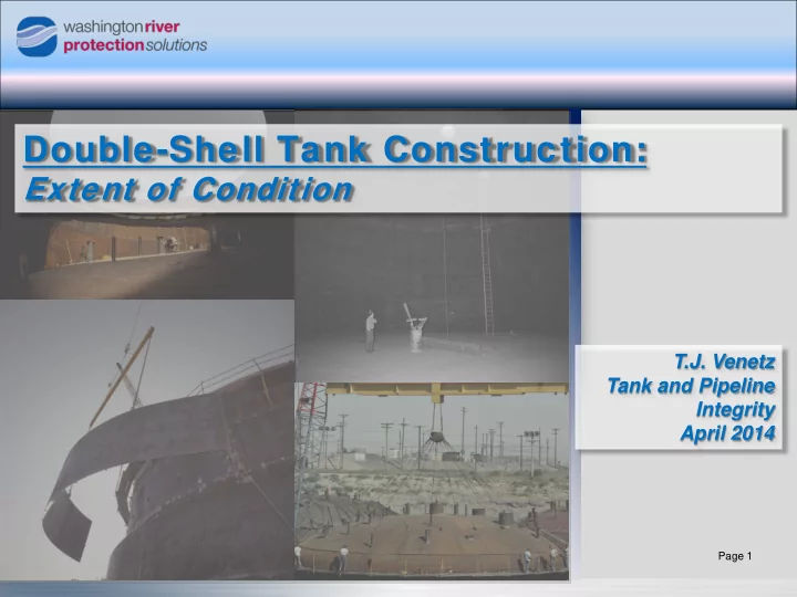
Tank Operations Contract Double-Shell Tank Construction: Extent of Condition T.J. Venetz Tank and Pipeline Integrity April 2014 Page 1 1 Tank Operations Double-Shell Tanks at Hanford Contract Double-Shell Tank Construction and Age as
Tank Operations Contract 1
Page 1
Tank Operations Contract 2
Page 2
Tank Farm Number
Construction Period Construction Project Initial Operation Service Life Current Age 241-AY 2 1968 – 1970 IAP-614 1971 40 43 241-AZ 2 1970 – 1974 HAP-647 1976 20 38 241-SY 3 1974 – 1976 B-101 1977 50 37 241-AW 6 1976 – 1979 B-120 1980 50 34 241-AN 7 1977 – 1980 B-130, B-170 1981 50 33 241-AP 8 1982 – 1986 B-340 1986 50 28 Total 28
Tank Operations Contract 3
Page 3
Tank Operations Contract 4
Page 4
Tank Farm Number of Tanks Construction Period Boxes Reviewed Phase 1 241-AY 2 1968 – 1970 11 241-AZ 2 1970 – 1974 15 241-SY 3 1974 – 1976 34 Phase 2 241-AW 6 1976 – 1979 64 241-AN 7 1977 – 1980 54 241-AP 8 1982 – 1986 63 Total 28 241
Tank Operations Contract 5
Page 5
Report Number Report Title
RPP-RPT-54817 241-AY-101 Tank Construction Extent of Condition Review for Tank Integrity RPP-RPT-54818 241-AZ Tank Farm Construction Extent of Condition Review for Tank Integrity RPP-RPT-54819 241-SY Tank Farm Construction Extent of Condition Review for Tank Integrity RPP-RPT-55981 241-AW Tank Farm Construction Extent of Condition Review for Tank Integrity RPP-RPT-55982 241-AN Tank Farm Construction Extent of Condition Review for Tank Integrity RPP-RPT-55983 241-AP Tank Farm Construction Extent of Condition Review for Tank Integrity
Tank Operations Contract 6
Page 6
Tank Farm Primary Contractor Project # 241-AY Pittsburgh-Des Moines (PDM) Steel Company IAP-614 241-AZ Pittsburgh-Des Moines (PDM) Steel Company HAP-647 241-SY Chicago Bridge and Iron (CBI) Company B-101 241-AW American Bridge (AB) Company B-120 241-AN American Bridge (AB) Company B-130, B-170 241-AP American Bridge (AB) Company B-340
Tank Operations Contract 7
Page 7
Tank Operations Contract 8
Page 8
11/12. Concrete Shell and Dome
Tank Operations Contract 9
Page 9
Tank Operations Contract 10
Page 10
Tank Farm Material Type Plate Thickness (in.) 241-AY ASTM A515, Gr 60 1/4 (0.25) 241-AZ ASTM A515, Gr 60 3/8 (0.375) 241-SY ASTM A516, Gr 65 3/8 (0.375) 241-AW ASTM A537, Class 1 3/8 (0.375) 241-AN ASTM A537, Class 1 3/8 (0.375) 241-AP ASTM A537, Class 1 3/8 (0.375)
Tank Operations Contract 11
Page 11
Tank Detail AY-101 Excessive distortion and bulges noted throughout. Maximum slope noted as much as 1 inch per foot. 6 places exceed 2 inch peak-to-valley tolerance. AY-102 Excessive distortion and bulges noted throughout. Maximum slope noted as much as 1 inch per foot. 22 places exceed 2 inch peak-to-valley tolerance. AZ-101 Only minor notation, no deficiencies or NCRs found. It was noted that kaolite thickness was increased due to an irregular secondary liner bottom. AZ-102 Only minor notation, no deficiencies or NCRs found. The log noted that the plate dropped 3/8 inch when kaolite was poured. SY-101 Out of tolerance in several areas, up to 5/8 inch per foot and an NCR was generated. SY-102 Out of tolerance in several areas, up to 13/16 inch per foot and an NCR was generated. Flattening attempts were unsuccessful. SY-103 Weld pattern changed, still out of tolerance, up to 1 inch per foot, NCR generated. Flattening attempts, including a 6000 lb. weight, were unsuccessful. AW-102 4 bulges identified. All slopes less than 3/4-in./ft. All 241-AW tank farm bulges were accepted based on an engineering evaluation of the 241-SY Bottom Flatness Study authored by Battelle Northwest. AW-106 19 bulges identified, all bulges less than 3/4 in./ft. and accepted as is. All 241-AW tank farm bulges were accepted based on an engineering evaluation of the 241-SY Bottom Flatness Study authored by Battelle Northwest.
Tank Operations Contract 12
Page 12
Castable Refractory Degradation Castable Refractory Repair with Reinforced Concrete
Tank Operations Contract 13
Page 13
– Similar perimeter condition and repair performed.
– Only minor cracking repairs required. – Issues with waste compatibility – decomposed in surrogate.
– Some minor cracking repairs required. – SY-102: Damage from cribbing – 5ft. x 8 ft. x 2.5 in. area replaced.
– AW-101: Part of Section D replaced with Enriched Lite Wate 50. – AW-102, AW-105, AW-106: Refractory chipped out and replaced. – Low compressive strength Switched to Lite Wate 70.
– AN-104: 8 ft. x 3/4 in. void between refractory and secondary liner. – Drilled hole in the refractory to fill with pourable grout.
– AP-108: Minor cracking repairs required.
Tank Operations Contract 14
Page 14
Tank Farm Material Type Plate Thickness (in.) 241-AY ASTM A515-65, Gr 60 3/8 (0.375) 241-AZ ASTM A515-69, Gr 60 1/2 (0.5) 241-SY ASTM A516-72, Gr 65 1/2 (0.5) 241-AW ASTM A537-74a, Class 1 1/2 (0.5) 241-AN ASTM A537-75, Class 1 1/2 (0.5) 241-AP ASTM A537-79, Class 1 1/2 (0.5)
Tank Operations Contract 15
Page 15
– SY-101: Several areas out-of-tolerance (Max height = 0.26 ft). Grouted in two locations. – SY-102: Initially out-of tolerance. Corrected when lowered. – SY-103: Several areas out-of-tolerance. Strain gauge monitoring and acoustic testing during hydrostatic testing used to accept stress levels.
lowered.
dead weight.
Tank Detail SY-101 Out of tolerance areas noted and plate repairs performed, causing new out of tolerance areas. Maximum bump height of 0.26 feet and bottom grouted in two locations to support primary. SY-102 Out of tolerance areas noted until primary was lowered and found to be acceptable. SY-103 Out of tolerance in several areas, up to 13/16 inch per foot. An NCR was generated, which was later accepted based on strain gauge monitoring and acoustic testing during hydrostatic test, showing stresses were acceptable. AN-102 Initial inspection found the tank bottom to have one out-of-tolerance location. NCR B-130-32 was generated. The NCR was later voided, as a resurvey of the tank bottom found it to be within tolerance. AP-104 Two out of tolerance areas noted until dead weight was placed on them. Re-survey showed the tank bottom to be within specified tolerances.
Tank Operations Contract 16
Page 16
241-AY 241-AZ 241-SY 241-AW 241-AN 241-AP
100% Visual – Primary and Secondary
100% Radiography – Primary and Secondary
Vacuum Leak Test 1
Liquid Penetrant 1
Magnetic Particle 2
Hydrostatic Leak Test – Primary 3
1 Used on tank bottoms and bottom knuckle, but not on vertical walls 2 Not used on AZ, SY, and AW secondary liner 3 Height varied with farm, always above maximum waste level and upper knuckle to
dome plate weld
Tank Operations Contract 17
Page 17
241-AY Tank Farm AY-101 10.2% AY-102 33.8% 241-AZ Tank Farm AZ-101 14.5% AZ-102 6.3% 241-SY Tank Farm SY-101 30.1% SY-102 21.9% SY-103 25.7% 241-AW Tank Farm AW-101 30% AW-102 31% AW-103 27% AW-104 34% AW-105 31% AW-106 24% 241-AN Tank Farm AN-101 13% AN-102 13% AN-103 9% AN-104 9% AN-105 15% AN-106 10% AN-107 20% 241-AP Tank Farm AP-101 6% AP-102 9% AP-103 10% AP-104 9% AP-105 12% AP-106 6% AP-107 7% AP-108 5%
Tank Operations Contract 18
Page 18
Tank Operations Contract 19
Page 19
– Difficulties with steaming Moisture in the refractory ( ). – Accurate temperature monitoring Faulty primary bottom thermocouples ( ).
241-AY Tank Farm AY-101 1000°F 3 hours 2 days to heat. AY-102 1000°F 3 hours 5 days to heat. 241-AZ Tank Farm AZ-101 1050°F 2 hours AZ-102 1000°F 3 hours 241-SY Tank Farm SY-101 1000°F 3 hours SY-102 1100°F 1 hour Steaming SY-103 1100°F 1 hour 241-AW Tank Farm AW-101 1100°F 1 hour AW-102 1000°F 3 hours AW-103 1000°F 3 hours AW-104 1000°F 3 hours AW-105 1000°F 3 hours Heavy Steaming AW-106 1000°F 3 hours Steaming 241-AN Tank Farm AN-101 1000°F 3 hours AN-102 1000°F 3 hours AN-103 1000°F 3 hours AN-104 1000°F 3 hours AN-105 1000°F 3 hours Steaming AN-106 1000°F 3 hours Steaming AN-107 1000°F 3 hours 241-AP Tank Farm AP-101 1000°F 3 hours AP-102 1000°F 3 hours AP-103 1000°F 3 hours AP-104 1000°F 3 hours AP-105 1000°F 3 hours AP-106 1000°F 3 hours AP-107 1000°F 3 hours AP-108 950°F 5 hours
Tank Operations Contract 20
Page 20
Tank Farm Fill Height Fill Duration 241-AY 39 ft. 24 hours 241-AZ 39 ft. 24 hours 241-SY 39 ft. 24 hours 241-AW 35 ft. 24 hours 241-AN 35 ft. 24 hours 241-AP 40 ft. 24 hours
Tank Operations Contract 21
Page 21
– Raw water Leads to minor pitting within the primary tank.
– Corrosion inhibitors and cathodic protection utilized.
Tank Fill Date Pump-out Date
AW-101 3/22/1978 12/19/1978 9 AW-102 4/11/1978 12/27/1978 8 AW-103 5/4/1978 12/14/1978 7 AW-104 5/23/1978 1/31/1979 8 AW-105 6/27/1978 12/13/1978 6 AW-106 7/6/1978 2/1/1979 7 AN-101 12/5/1978 8/7/1979 8 AN-102 12/13/1978 7/27/1979 7 AN-103 1/4/1979 7/25/1979 7 AN-104 10/11/1978 8/6/1979 10 AN-105 1/31/1979 8/1/1979 6 AN-106 2/14/1979 7/26/1979 5 AN-107 2/26/1979 7/30/1979 5
Tank Operations Contract 22
Page 22
Tank Operations Contract 23
Page 23
Tank Operations Contract 24
Page 24
Tank Operations Contract 25
Page 25
Travis Barnes
Mechanical Engineer
Kayle Boomer
Chemical Engineer – Technical Lead
Ted Venetz
Chemical Engineer – Principal Engineer
Gretchen Reeploeg
Mechanical Engineer
Del Scott
Project Manager
Jason Gunter
Mechanical Engineer