
SLIDE 1
William Sandqvist william@kth.se
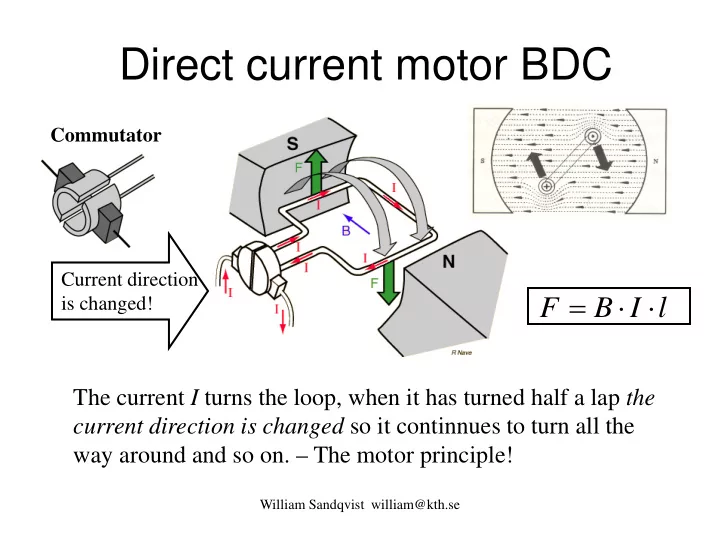
Direct current motor BDC
l I B F ⋅ ⋅ =
The current I turns the loop, when it has turned half a lap the current direction is changed so it continnues to turn all the way around and so on. – The motor principle!
Current direction is changed! Commutator