
SLIDE 1
1
- Prof. S. Ben-Yaakov , Dc-DC Converters
[7- 1]
Half Bridge, Full Bridge, Push-Pull, Cuk, SEPIC
- Prof. S. Ben-Yaakov , Dc-DC Converters
[7- 2]
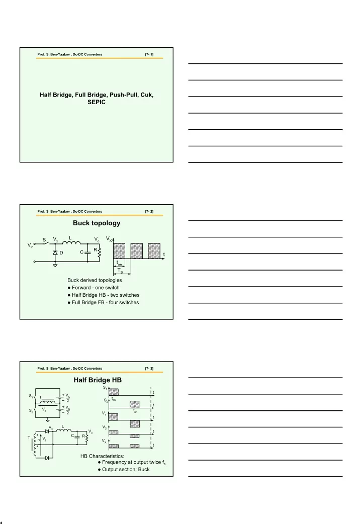
Buck derived topologies
Forward - one switch Half Bridge HB - two switches Full Bridge FB - four switches
t VX TS ton
S Vin D L C R Vx Vo
Buck topology
- Prof. S. Ben-Yaakov , Dc-DC Converters