
SLIDE 1
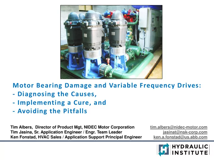
Motor Bearing Damage and Variable Frequency Drives:
- Diagnosing the Causes,
- Implementing a Cure, and
- Avoiding the Pitfalls
Tim Albers, Director of Product Mgt, NIDEC Motor Corporation tim.albers@nidec-motor.com Tim Jasina, Sr. Application Engineer / Engr. Team Leader jasinat@nsk-corp.com Ken Fonstad, HVAC Sales / Application Support Principal Engineer ken.a.fonstad@us.abb.com