
SLIDE 1
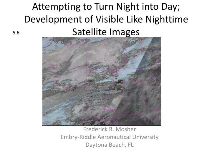
Attempting to Turn Night into Day; Development of Visible Like Nighttime Satellite Images
Frederick R. Mosher Embry-Riddle Aeronautical University Daytona Beach, FL
5.6
Development of Visible Like Nighttime Satellite Images 5.6 - - PowerPoint PPT Presentation
Attempting to Turn Night into Day; Development of Visible Like Nighttime Satellite Images 5.6 Frederick R. Mosher Embry-Riddle Aeronautical University Daytona Beach, FL Satellite Support for Aviation Briefings Aviation interests are
Frederick R. Mosher Embry-Riddle Aeronautical University Daytona Beach, FL
5.6
Visible, Infrared, and Water Vapor images from Aviation Weather Center, Dec. 9, 13Z.
Nighttime Dec. 9, 11:45Z Sunrise 13:15Z Daylight at 14:00Z
different brightness ranges.
between 3.9 and 11 micron channels.
11 and 13.5 micron channels.
with difference brightness ranges.
and low images and tint high image a light blue.
IR Image Water Vapor Image IR image showing pixels which have been corrected with WV temperature.
Visible Image Brightness Normalized Visible Image
High Visible Pixels Low Visible Pixels Merged with Enhancement table stretching both sub- images and tinting high image blue.
Merged Nighttime Fog and Height Images Merged Night and Visible Images