DEVELOPMENT OF SINGLE CRYSTALLINE SILICON SOLAR CELLS LAY-DOWN - - PDF document

development of single crystalline silicon solar cells lay
SMART_READER_LITE
LIVE PREVIEW

DEVELOPMENT OF SINGLE CRYSTALLINE SILICON SOLAR CELLS LAY-DOWN - - PDF document

18 TH INTERNATIONAL CONFERENCE ON COMPOSITE MATERIALS DEVELOPMENT OF SINGLE CRYSTALLINE SILICON SOLAR CELLS LAY-DOWN PROCESS ON COMPOSITES J. C. Kim 1 , I. H. Choi 2 , D. H. Kim 1 , S. K. Cheong 1 * 1 Mechanical Engineering, Seoul National Uni. of


slide-1
SLIDE 1

18TH INTERNATIONAL CONFERENCE ON COMPOSITE MATERIALS

1 Introduction Recently, photovoltaic power energy appears to be

  • ne of the major technologies for the global sheared

concerns in protecting environment. Up until now, many studies for the development of solar cell have focused on better stability and higher efficiency. However, the solar industry will be developed for combining solar cells to various kinds of structures. Light-weight composite is suitable for the structures which need high specific strength and stiffness. Nowadays the solar cell bonding to skins of buildings, vehicles, or electrical devices is a big issue [1]. The research paper on bonding thin-film

silicon solar cell to CFRP composite was published

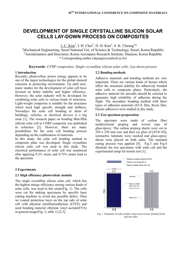
in reference [2]. However, there are many possibilities for the solar cell bonding process depending on the combination of materials. In this study, the solar cell bonding method to composite plate was developed. Single crystalline silicon solar cell was used in this study. The electrical performance of solar cell was monitored after applying 0.3% strain and 0.75% strain load to the specimen. 2 Experiments 2.1 High efficiency photovoltaic module The single crystalline silicon solar cell, which has the highest energy efficiency among various kinds of solar cells, was used in this study(Fig. 1). The cells were cut for making specimens by specific laser cutting machine to avoid any possible defect. Then we coated protection layer on the top side of solar cell with ethylene tetrafluoroethylene (ETFE) and used bonding material ethylene vinyl acetate(EVA) in general usage(Fig. 2, table 1) [2,3]. 2.2 Bonding methods Adhesive materials and bonding methods are very

  • important. There are various kinds of factors which

affect the structural stability for adhesively bonded solar cells to composite plates. Particularly, the adhesive material for aircrafts should be selected to guarantee high reliability of adhesion during the

  • flight. The secondary bonding method with three

types of adhesion materials (EVA film, Resin film, Elastic adhesive) were studied in this study. 2.3 Test specimen preparation The specimen were made

  • f

carbon fiber unidirectional prepreg and woven type

  • f

glass/epoxy. The carbon prepreg sheets were cut to 250 x 250 mm size and then six plies of [45/0/-45]s symmetric laminate were stacked and glass-epoxy sheets were placed on both sides. The standard curing process was applied [4]. Fig.3 and Fig.4 illustrate the test specimens with solar cell and the experimental setup for tensile test [1].

Ethylene tetrafluoroethylene (ETFE) Ethylene vinyl acetate(EVA) Single crystalline silicon solar cell Electrode SIngle crystalline silicon solar cell (with protection layer) Ribbon wire

24.8 mm

  • Fig. 1. Schematic of solar module; (top) cross-section, (bottom) front

and rear sides.

DEVELOPMENT OF SINGLE CRYSTALLINE SILICON SOLAR CELLS LAY-DOWN PROCESS ON COMPOSITES

  • J. C. Kim1, I. H. Choi2, D. H. Kim1, S. K. Cheong1*

1Mechanical Engineering, Seoul National Uni. of Science & Technology, Seoul, Korea Republic 2Aerodynamics and Structures, Korea Aerospace Research Institute, Daejeon, Korea Republic

* Corresponding author (skjung@seoultech.ac.kr)

Keywords: CFRP composites; Single crystalline silicon solar cells; Lay-down process

slide-2
SLIDE 2

0.0 0.1 0.2 0.3 0.4 0.5 0.6 0.7 10 20 30 40 50

Current Density, J (mA/cm

2)

Voltage(V) Single crystalline silicon solar module Specimen no.1 Specimen no.2 Specimen no.3 Specimen no.4 Specimen no.5 Specimen no.6 Specimen no.7 Specimen no.8

  • Fig. 2. Performance characterization of as-received single crystalline

silicon solar module.

Voc(V) Jsc(mA/cm2) Fill factor Efficiency(%) Avg.

0.65 44.01 0.6241 17.49

Table 1 The average performance of as-received single crystalline silicon solar modules.

  • Fig. 3. Description of test specimen.
  • Fig. 4. Experimental setup for tensile test .

3 Test results 3.1 Electrical properties

  • Fig. 5 shows the solar modules J-V characteristics of

each specimen after tensile test [3]. When EAV and Resin film were used as bonding materials, their electrical performance were gradually decreased after test, whereas elastic adhesive bonding case has no significant decreasing trend after test.

  • Fig. 5. Performance characteristics of a solar modules after tensile test;

(top) EVA film; (middle) Resin film; (bottom) Elastic adhesive.

0.0 0.1 0.2 0.3 0.4 0.5 0.6 0.7 10 20 30 40 50

η:10.15% η:13.7% η:17%

η: energy conversion efficiency

Current Density, J (mA/cm

2)

Voltage(V) Resin film As-received After tensile test(0.3% strain) After tensile test(0.75% strain)

0.0 0.1 0.2 0.3 0.4 0.5 0.6 0.7 10 20 30 40 50

η:17.91% η:17.87% η:18.12%

η: energy conversion efficiency

Current Density, J (mA/cm

2)

Voltage (V)

Elastic Adhesive As-received After tensile test(0.3% strain) After tensile test(0.75% strain)

0.0 0.1 0.2 0.3 0.4 0.5 0.6 0.7 10 20 30 40 50

η:7.6% η:13.23% η:17% Current Density, J (mA/cm

2)

Voltage(V)

EVA film As-received After tensile test(0.3% strain) After tensile test(0.75% strain)

η: energy conversion efficiency

slide-3
SLIDE 3

`

3.2 Adhesive thickness control Figure 5 shows that the elastic adhesive is suitable for bonding material. Figure 6 shows the effect of adhesive thickness on electrical performance after applying load.

  • Fig. 6. Performance characteristics of solar modules various adhesive

thickness at 0.75% strain (120μm, 240μm, 360μm, 460μm, 570μm).

4 Summaries The single crystalline silicon solar module lay-down process was developed on the CFRP using the secondary-bonding method. Elastic adhesive material was suitable for maintaining good electrical performance regardless of loading or adhesion

  • thickness. The basic principles for bonding brittle

silicon cell to the various kinds of structural surface can be predicted. Further study will be performed under various temperature conditions.

0.0 0.1 0.2 0.3 0.4 0.5 0.6 0.7 10 20 30 40 50

η: energy conversion efficiency, FF: fill factor

Current Density, J (mA/cm

2)

Voltage (V)

Elastic Adhesive 120 micron (0.75% strain)

η: 19.51% FF: 0.6554

0.0 0.1 0.2 0.3 0.4 0.5 0.6 0.7 10 20 30 40 50

η: energy conversion efficiency, FF: fill factor

Current Density, J (mA/cm

2)

Voltage (V)

Elastic Adhesive 240 micron (0.75% strain)

η: 19.00% FF: 0.6534

0.0 0.1 0.2 0.3 0.4 0.5 0.6 0.7 10 20 30 40 50

Current Density, J (mA/cm

2)

Voltage (V)

Elastic Adhesive 360 micron (0.75% strain)

η: energy conversion efficiency, FF: fill factor η: 19.82% FF: 0.6565

0.0 0.1 0.2 0.3 0.4 0.5 0.6 0.7 10 20 30 40 50

Current Density, J (mA/cm

2)

Voltage (V)

Elastic Adhesive 460 micron (0.75% strain)

η: energy conversion efficiency, FF: fill factor η: 19.61% FF: 0.6616

0.0 0.1 0.2 0.3 0.4 0.5 0.6 0.7 10 20 30 40 50

Current Density, J (mA/cm

2)

Voltage (V)

Elastic Adhesive 570 micron (0.75% strain)

η: energy conversion efficiency, FF: fill factor η: 21.22% FF: 0.6752

slide-4
SLIDE 4

References

[1] J. C. Kim, Y. S Lee, J. H. Lee, I. K. Choi, D. H. Kim,

  • S. K. Cheong “A study on the solar cell lay-down for

solar powered aircraft using secondary-bonding method”. KSME, pp 399-403, 2010. [2] K. J. Maung, H. T. Hahn, Y.S. Ju “Multifunctional integration of thin-film silicon solar cells on carbon- fiber-reinforced epoxy composites”. Solar Energy,

  • Vol. 84, pp 450-458, 2010.

[3] A. G. Aberle “Fabrication and characterisation of crystalline silicon thin-film materials for solar cells”. Thin Solid Films, Vol. 511-512, pp 26-34, 2006. [4] S. H. Lee, H. Noguchi, S. K. Cheong “Tensile properties and fatigue characteristics of hybrid composites with non-woven carbon tissue”. International Journal of Fatigue, Vol. 24, pp 397- 405, 2008. [5] J. A. Foster, G. S. Aglietti “The thermal environment encountered in space by a multifunctional solar array”. Aerospace Science and Technology, Vol. 12, pp 213-219, 2010.