
SLIDE 1
Development of Semi-empirical Thermal Conductivity Model of U-Mo/Al Dispersion Fuel
Tae Won Cho*, Yong Jin Jeong, Kyu Hong Lee, Sung Hwan Kim, Ki Nam Kim, Jong Man Park Research Reactor Fuel Development Division, Korea Atomic Energy Research Institute, 111, Daedeok-daero 989beon-gil, Yuseong-gu, Daejeon, Republic of Korea
*Corresponding author: twcho@kaeri.re.kr
- 1. Introduction
U-Mo/Al dispersion fuel has been developed for a candidate high-performance fuel of high-power research and test reactors worldwide. U-Mo/Al dispersion fuel shows conspicuous microstructure changes during irradiation, which is dependent on the fuel temperature. In this respect, it is important to estimate temperature distribution in the fuel. In our previous works, the thermal properties of U- Mo/Al dispersion fuel were measured and investigated some microstructure effects [1, 2]. However, it is difficult to apply the measured data to fuel performance analysis since it is applicable only to limited fuel
- conditions. Therefore, it is necessary to develop a semi-
empirical model, which is conveniently applicable to various fuel conditions.
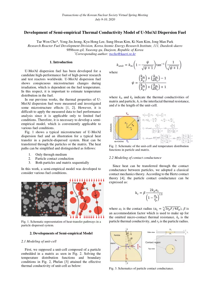
- Fig. 1 shows a typical microstructure of U-Mo/Al
dispersion fuel and an illustration for a typical heat transfer in a particle-dispersed system. Heat can be transferred through the particles or the matrix. The heat paths can be simplified and distinguished as follows: 1. Only through medium 2. Particle contact conduction 3. Both particles and matrix sequentially In this work, a semi-empirical model was developed to consider various fuel conditions.
- Fig. 1. Schematic representation of heat-transfer pathways in a
particle dispersed system.
- 2. Developments of Semi-empirical Model
2.1 Modeling of unit-cell First, we supposed a unit-cell composed of a particle embedded in a matrix as seen in Fig. 2. Solving the temperature distribution functions and boundary conditions in Fig. 2, Phelan [3] attained the effective thermal conductivity of unit-cell as below: 𝑙𝑣𝑜𝑗𝑢 = 𝑙𝑛 (1 − 𝜔 √𝜔 + 1 ) tan−1 ( 1 √𝜔 + 1 ) where 𝜔 = (𝑙𝑛 𝑙𝑞 ) + ( 𝑙𝑛 𝑒ℎ𝑑) − 1 (𝑙𝑛 𝑙𝑞 ) + ( 𝑙𝑛 𝑒ℎ𝑑) + 1 where km and kp indicate the thermal conductivities of matrix and particle, hc is the interfacial thermal resistance, and d is the length of the unit-cell.
- Fig. 2. Schematic of the unit-cell and temperature distribution
functions in particle and matrix.
2.2 Modeling of contact conductance Since heat can be transferred through the contact conductance between particles, we adopted a classical contact mechanics theory. According to the Hertz contact theory [4], the particle contact conductance can be expressed as: kc = 𝛾 2𝑙𝑞𝑏𝑀 (1 − 𝑏𝑀 𝑠
𝑞 ) 1.5
where aL is the contact radius (𝑏𝑀 = √3𝑠
𝑞𝐺 4𝐹𝑞
⁄
3
), β is an accommodation factor which is used to make up for the omitted micro-contact thermal resistance, kp is the particle thermal conductivity, and rp is the particle radius.
- Fig. 3. Schematics of particle contact conductance.
Path #1 Path #2 Path #3
Transactions of the Korean Nuclear Society Virtual Spring Meeting July 9-10, 2020