
SLIDE 1
18TH INTERNATIONAL CONFERENCE ON COMPOSITE MATERIALS
1 General Introduction KARI and Korean Air have developed, manufactured and tested a dimensional stable and load carrying CFRP Camera Structure for a spaceborne optical camera. The main purpose of this project is to establish the manufacturing process and the performance verification method
- f CFRP CAMERA STRUCTURE in Korean
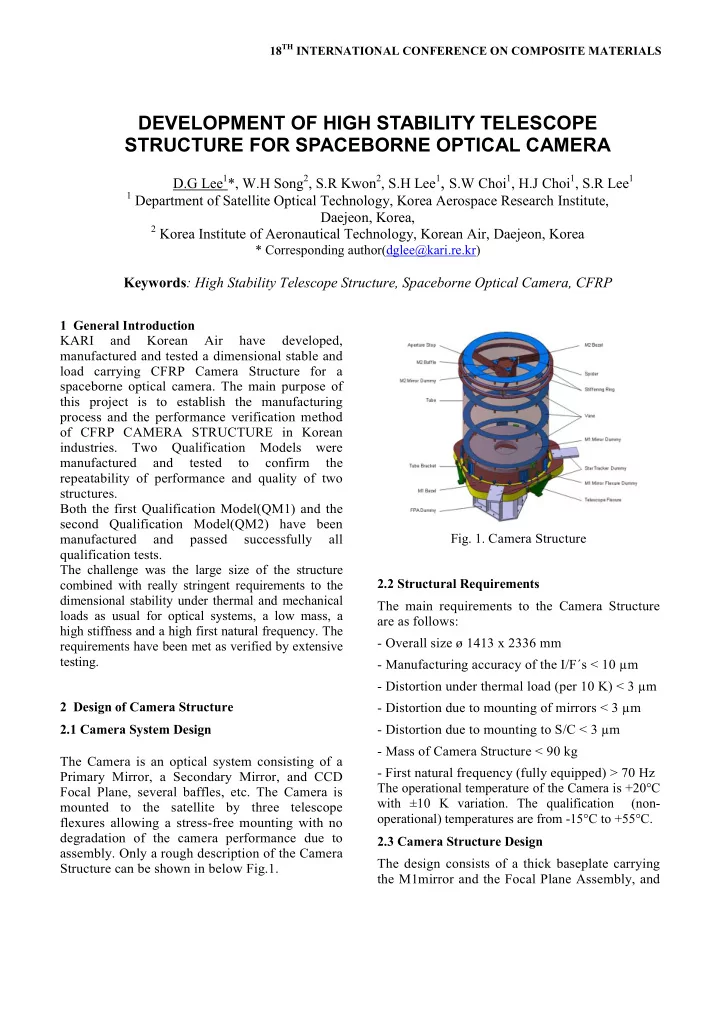
industries. Two Qualification Models were manufactured and tested to confirm the repeatability of performance and quality of two structures. Both the first Qualification Model(QM1) and the second Qualification Model(QM2) have been manufactured and passed successfully all qualification tests. The challenge was the large size of the structure combined with really stringent requirements to the dimensional stability under thermal and mechanical loads as usual for optical systems, a low mass, a high stiffness and a high first natural frequency. The requirements have been met as verified by extensive testing. 2 Design of Camera Structure 2.1 Camera System Design The Camera is an optical system consisting of a Primary Mirror, a Secondary Mirror, and CCD Focal Plane, several baffles, etc. The Camera is mounted to the satellite by three telescope flexures allowing a stress-free mounting with no degradation of the camera performance due to
- assembly. Only a rough description of the Camera
Structure can be shown in below Fig.1.
- Fig. 1. Camera Structure
2.2 Structural Requirements The main requirements to the Camera Structure are as follows:
- Overall size ø 1413 x 2336 mm
- Manufacturing accuracy of the I/F´s < 10 µm
- Distortion under thermal load (per 10 K) < 3 µm
- Distortion due to mounting of mirrors < 3 µm
- Distortion due to mounting to S/C < 3 µm
- Mass of Camera Structure < 90 kg
- First natural frequency (fully equipped) > 70 Hz
The operational temperature of the Camera is +20°C with ±10 K variation. The qualification (non-
- perational) temperatures are from -15°C to +55°C.