development of devices and systems for adaptive optics
play

Development of devices and systems for adaptive optics J.Mocci, - PowerPoint PPT Presentation

Development of devices and systems for adaptive optics J.Mocci, R.Muradore, F.Mousavi, P.Vallone, P.Villoresi, S.Bonora CNR-Institute of Photonics and Nanotechnology, via Trasea 7, 35131, Padova, Italy Universit degli Studi di Verona


  1. Development of devices and systems for adaptive optics J.Mocci, R.Muradore, F.Mousavi, P.Vallone, P.Villoresi, S.Bonora CNR-Institute of Photonics and Nanotechnology, via Trasea 7, 35131, Padova, Italy Università degli Studi di Verona Università degli Studi di Padova

  2. Aberrations in lasers Aberrations from: Thermally induced phase aberrations With AO After Before correction correction In lasers aberrations reduce the intensity Without AO

  3. Deformable mirror technology Piezoelectric bimorph DM Converse piezoelectric effect PZT expands and bends the glas substrate 40mm x 40mm Hilase Advantages: Possible to scale up the size, robust, any coating (metallic or dielectric) Pulse shaping

  4. Adaptive optics activity Our deformable mirrors: Bimorph (metallic or dielectric) Applications: Mid IR pulse shaper Application of DMs to pulse compression and shaping ultrashort lasers UV, Vis, NIR and Mid-IR, High peak /High avg power lasers S.Wall et al, Quantum interference between charge excitation paths in a solid-state Mott insulator, Nature Physics , 114-118, Vol. 7, 2011 REVIEW: D.Brida et al, Few-optical-cycle pulses tunable from the visible to the mid-infrared by optical parametric amplifiers J. Opt. 12 (2010) 013001 DMs and Deformable diffraction grating for XUV ultrashort pulses S. Bonora, et al. Active diffraction gratings: Development and tests , Rev. Sci. Instrum . 83, 123106 (2012); 
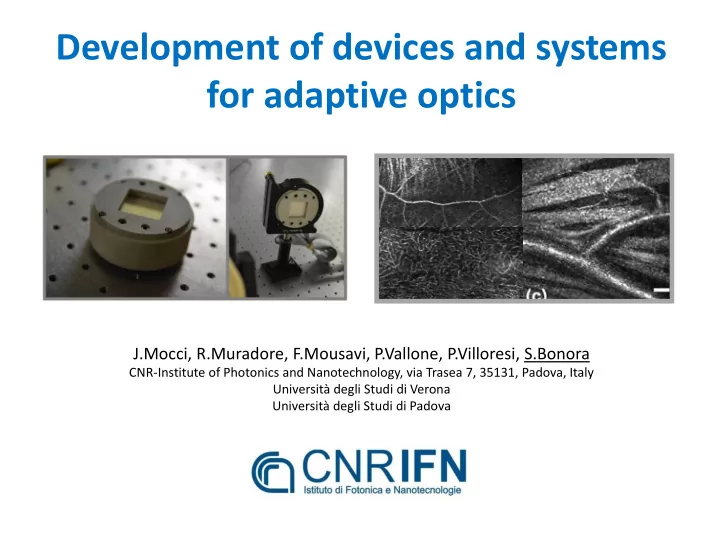
Medical/microscopy imaging (2 Photons, OCT, confocal) S. Bonora,et all " Wavefront correction and high-resolution in vivo OCT imaging with an objective integrated Def. Diffraction multi-actuator adaptive lens," Opt. Express 23, 21931-21941 (2015) Grating K.S.K. Wong, et al , “I n vivo imaging of human photoreceptor mosaic with wavefront sensorless adaptive optics o ptical coherence tomography”, Biomed. Opt. Express 6, 580 -590 (2015) AO on AO off OCT In vivo retinal cones image In human eye

  5. CFEL RAL (Hamburg) (Oxford) Hilase (Prague) FDA LLNL (Livermore) ILIL (Pisa) High power lasers Femtosecond lasers – Pulse shaping Medical Imaging

  6. What we are asked for: • High performance: • Technical requirements: • Dimensioni 25mm – 100mm (we are looking into 20cm DM) • Stroke >20um • Damage Threshold > 20J/cm 2 (ns), > 5J/cm 2 (fs) • Broad bandwidth and Low GDD (fs) • Actuators 32 – 144 • Response time 10Hz (DM response time about 1ms) • Vacuum compatible (10 -4 mbar) • Quality • Preliminary simulations -> DM desing • Collaboration for installation/Participate to experiments • Spares involve industrial • Quality ISO certification, Warranty • Reliable electronics partners

  7. Design example: Deformable mirrors for Hilase J.Pilar, A.Lucianetti, S.Bonora HiLASE project, Institute of Physics AS CR, Na Slovance 2, 18221, Prague, Czech Republic CNR-Institute for Photonics and Nanotechnology, Via Trasea 7, 35131, Padova, Italy HILASE High average power cryogenically-cooled diode-pumped solid-state laser system Developed deformable mirrors for: Hilase (Czech republic) and Dipole (UK) Energy: 10J Duration: 10ns Rep rate: 10Hz Size: 27mm x 27mm, Wavelength: 1030nm 7x7 actuators

  8. HiLASE & ELI Beamlines avvcca 8

  9. Simulations and DM design Laser Themo-Optical DM model Model FEM others Example of Actuator layout 1) Jan Pilar, et al, Design and optimization of an adaptive optics system for a high-average-power multi-slab laser (HiLASE), Applied Optics, Vol. 53, Issue 15, pp. 3255-3261 (2014) * selected by the Editors, for publication in the Virtual Journal for Biomedical Optics (VJBO), Vol. 9, Iss. 7 — Jul. 9, 2014 2) A.Lucianetti, et al, Design of a kJ-class HiLASE laser as a driver for inertial fusion energy, High Power Laser Science and Engineering, (2014), Vol. 2, e13

  10. DM characterization

  11. Closed loop working Comparison of the laser spot before and after the closed loop activation

  12. Our recent DMs for High Power laser Pisa (ITA) ILIL lab Virgo (ITA) Livermore 5J, 800nm, 100fs 0.85ns, 740-900nm, 0.5J 2W, 10.6um, CW Low GDD <100fs 2 75mm aperture 144 actuators 5J/cm 2

  13. Adaptive lens and application in sensorless microscopy

  14. Adaptive lens: properties 18 pzt actuators outside the clear aperture Optical power: 1.4D Clear aperture: 10mm Transmission: visible NIR (TBM) Initial aberration: 0.22waves rms Corrected with about 25% rms voltage range Technology: PZT bimorph Voltage range: -125V/+125V Generates aberrations up to the 4 th order Adaptive lens mounted on a camera objective

  15. Closed loop control with wavefront sensor

  16. Closed loop and Far Field It is then possible to generate any aberration up to the 4 th Zernike order

  17. Use of the Adaptive Lens in in-vivo imaging Source b) c) a) Source Source BS Detector Control Deformable BS BS Detector System Mirror Control Detector BS WFS 2 1 Lente adattiva MAL Objective Objective Objective Sample Sample Sample

  18. Key elements: • Wavefront sensorless algorithm 1 • An adaptive lens that can replace a deformable mirror 2 Key properties of the adaptive lens: - Open loop control : we need to operate the Adaptive Lens without the wavefront sensor! - In Vivo : fast response time!

  19. Scan sequence Defocus «Astigmatism» Coma Spherical Ab. Relaxation time: 5 oscillations +/- about 300ms Trefoil 11 points per aberrations About 0.5 sec for each aberration

  20. Adaptive Lens: Compact OCT Opthalmoscope System realized at the Simon Fraser University (Vancouver)

  21. Electronic driver Electronics MUST BE: reliable, easy to use, compact Integrate the electronic inside the DM

  22. F.Mousavi,P.Villoresi, G.Vallone

  23. Active projects • DM for CW fiber lasers 2kW – Salvagnini Spa • Cutting and welding • Adaptive Lenses – Ophtalmic and Vision • UC Davis, SFU • Fast Wavefront sensor • University of Verona • DM for XUV synchrotron radiation (13nm – 100nm) • Desy, Hamburg • Integrate the electronic inside the DM • Develop larger DMs: 20cm diameter Thank you! stefano.bonora@dei.unipd.it

Download Presentation
Download Policy: The content available on the website is offered to you 'AS IS' for your personal information and use only. It cannot be commercialized, licensed, or distributed on other websites without prior consent from the author. To download a presentation, simply click this link. If you encounter any difficulties during the download process, it's possible that the publisher has removed the file from their server.

Recommend


More recommend