
SLIDE 1
nano@nanogune.eu I www.nanogune.eu nano@nanogune.eu I www.nanogune.eu
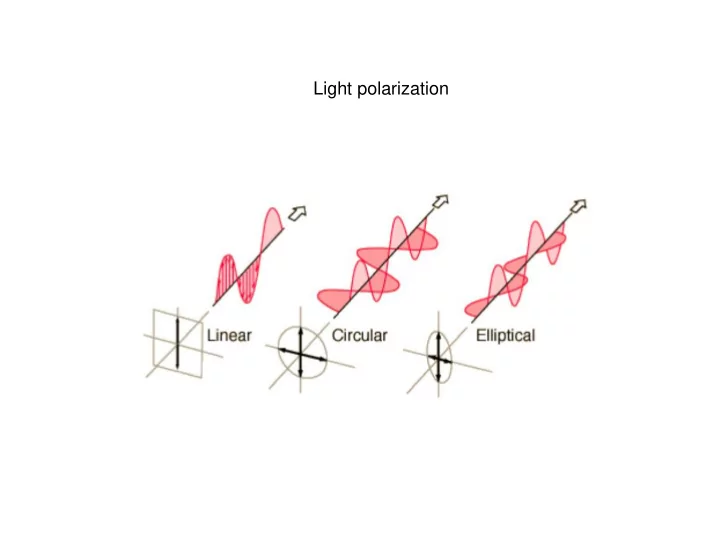
Light polarization nano@nanogune.eu I www.nanogune.eu - - PowerPoint PPT Presentation
Light polarization nano@nanogune.eu I www.nanogune.eu nano@nanogune.eu I www.nanogune.eu Jones vectors and matrices Since light is composed of oscillating electric and magnetic fields, Jones reasoned that the most natural way to represent
nano@nanogune.eu I www.nanogune.eu nano@nanogune.eu I www.nanogune.eu
nano@nanogune.eu I www.nanogune.eu nano@nanogune.eu I www.nanogune.eu
Since light is composed of oscillating electric and magnetic fields, Jones reasoned that the most natural way to represent light is in terms of the electric field vector. When written as a column vector, this vector is known as a Jones vector and has the form:
These values can be complex numbers, so both amplitude and phase information is
phases of the vector components. Therefore Jones vectors can be normalized and common phase factors can be neglected. Horizontal and vertical linear polarization states (reflection plane xz).
nano@nanogune.eu I www.nanogune.eu nano@nanogune.eu I www.nanogune.eu
nano@nanogune.eu I www.nanogune.eu nano@nanogune.eu I www.nanogune.eu
i i
i
2 2 2
K
2 2 2
K
nano@nanogune.eu I www.nanogune.eu nano@nanogune.eu I www.nanogune.eu
1
1 11 12 1 21 22 x x y y x y
x
1
x x x y
22 21 12 11
nano@nanogune.eu I www.nanogune.eu nano@nanogune.eu I www.nanogune.eu
y
HWP
QWP
nano@nanogune.eu I www.nanogune.eu nano@nanogune.eu I www.nanogune.eu
nano@nanogune.eu I www.nanogune.eu nano@nanogune.eu I www.nanogune.eu
Half-wave plate, fast axis horizontal Half-wave plate, fast axis vertical General retarder, fast axis horizontal In terms of waves (wavelength l), this is a retarder l*j/2p
Retardation l/2 Retardation l/2 Retardation l/4 Retardation l/4
nano@nanogune.eu I www.nanogune.eu nano@nanogune.eu I www.nanogune.eu
1 1
1 1 1 1 1
− − −
1
−
nano@nanogune.eu I www.nanogune.eu nano@nanogune.eu I www.nanogune.eu
x
1
−
x
2 2
x
x
x
nano@nanogune.eu I www.nanogune.eu nano@nanogune.eu I www.nanogune.eu
nano@nanogune.eu I www.nanogune.eu nano@nanogune.eu I www.nanogune.eu
1 3 2 1
nano@nanogune.eu I www.nanogune.eu nano@nanogune.eu I www.nanogune.eu
y x
1 y x
1
y x
1
x x y y x
y x
nano@nanogune.eu I www.nanogune.eu nano@nanogune.eu I www.nanogune.eu
ss sp ps pp
ss pp
iTM rTM pp
E E r =
iTE rTE ss
E E r =
iTE rTM ps
E E r =
iTM rTE sp
E E r =
Fresnell reflection coefficients
x y x z y z
= ˆ
Dielectric tensor
is ip
rs rp
x z y p s p s θ θ s p s p s p Reflected Light z θ x Transmitted Light Polarization Plane Sample
rs rp
is ip
nano@nanogune.eu I www.nanogune.eu nano@nanogune.eu I www.nanogune.eu 1 2 2 2 1 2 2 1 2 1 2 1
pp+ rpp M my
ss sp ps pp
nano@nanogune.eu I www.nanogune.eu nano@nanogune.eu I www.nanogune.eu
nano@nanogune.eu I www.nanogune.eu nano@nanogune.eu I www.nanogune.eu
( )
+ = = =
sin cos 1 1 ~ i r r e r r r r E
pp sp i pp sp sp pp r
pp sp
ss ps
pp sp
ss ps
pp sp K K
pp sp K K
cos Re
pp sp pp sp
r r r r = sin Im
pp sp pp sp
r r r r =
2 2 2
1 cos 2 cos 2 2 tan b b r r r r
sp pp sp pp K
− = − = q
2 2 2
sp pp sp pp K
Elliptically polarized light Normalized representation
a b Eox Eoy x y
K qK
E(z,t)
nano@nanogune.eu I www.nanogune.eu nano@nanogune.eu I www.nanogune.eu
qK K
pp sp
ss ps
pp sp
ss ps
Birifringence Dichroism
P-MOKE: eigenmodes are LCP and RCP polarized EMs
− =
xx xx xy xy xx
~ − =
xx yz yz xx xx
~
nano@nanogune.eu I www.nanogune.eu nano@nanogune.eu I www.nanogune.eu
nano@nanogune.eu I www.nanogune.eu nano@nanogune.eu I www.nanogune.eu
Io
pp + rm ppmy
The reflected beam is p-polarized. Variation of intensity and phase.
JMMM 226-230, 1686 (2001); JMMM 242-245, 964 (2002). M
pp
ppmy
nano@nanogune.eu I www.nanogune.eu nano@nanogune.eu I www.nanogune.eu
− = bi Eo 1 ~ = i AQWP 1 ~ = = = − = h h h h sin cos cos sin 1 1 1 1 ~' b bi i E
0(cos
= = cos sin cos 1 ~ '
'
h h h E
h
2 2 ' '
cos ) ~ ( = = E I
Adding an analyzed (i.e. A polarazier in front of the detector I get h (Malus law)
nano@nanogune.eu I www.nanogune.eu nano@nanogune.eu I www.nanogune.eu
nano@nanogune.eu I www.nanogune.eu nano@nanogune.eu I www.nanogune.eu
wollastone
wollastone
nano@nanogune.eu I www.nanogune.eu nano@nanogune.eu I www.nanogune.eu
Modulation polarization technique for recording the longitudinal and polar Kerr effects, which are proportional to the magnetization components mx mz..
POLARIZER Glan-Thompson PHOTOELASTIC MODULATOR (50kHz) ORIGINAL ELLIPTICTY MODULATED ELLIPTICTY PREAMPLIFIED PHOTODIODE POLARIZER HeNe LASER p-polarized beam s-p polarized reflected beam (elliptical polarization)
Electromagnet
More details in: P. Vavassori, Appl. Phys. Lett. 77, 1605 (2000)
nano@nanogune.eu I www.nanogune.eu nano@nanogune.eu I www.nanogune.eu
* 2 ss ss ss DC
r r r I = =
Now:
* * *
ss ps ps ss ss ps
* * *
ss ps ps ss ss ps
− =
) ( ) ( 1 ) (
Im tan 2 4
ss pp ps sp s p
r r J i
w
=
) ( ) ( 2 ) ( 2
Re tan 2 4
ss pp ps sp s p
r r J i
w
m
S-pol (I considered here the general case
extinction with the initial polarizer)
nano@nanogune.eu I www.nanogune.eu nano@nanogune.eu I www.nanogune.eu
PEM rotated 45o