Development of Advanced Small Diameter Submarine Cable Mareto - - PowerPoint PPT Presentation

development of advanced small diameter submarine cable
SMART_READER_LITE
LIVE PREVIEW

Development of Advanced Small Diameter Submarine Cable Mareto - - PowerPoint PPT Presentation

Development of Advanced Small Diameter Submarine Cable Mareto Sakaguchi, Nobuaki Matsuda, Yasushi Hasegawa, Osamu Nagatomi, Juan Carlos Aquino OCC Corporation JAPAN Introduction In this paper we describe the development of OCC-SC500, an


slide-1
SLIDE 1

Development of Advanced Small Diameter Submarine Cable

Mareto Sakaguchi, Nobuaki Matsuda, Yasushi Hasegawa, Osamu Nagatomi, Juan Carlos Aquino OCC Corporation JAPAN

Cable Design

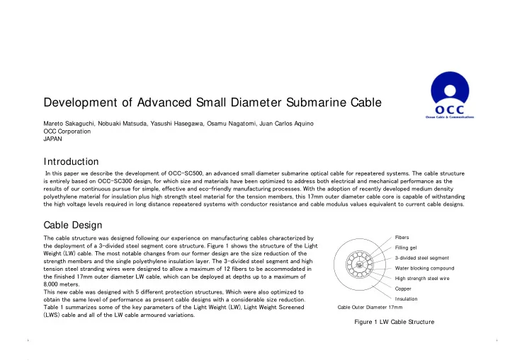
In this paper we describe the development of OCC-SC500, an advanced small diameter submarine optical cable for repeatered systems. The cable structure is entirely based on OCC-SC300 design, for which size and materials have been optimized to address both electrical and mechanical performance as the results of our continuous pursue for simple, effective and eco-friendly manufacturing processes. With the adoption of recently developed medium density polyethylene material for insulation plus high strength steel material for the tension members, this 17mm outer diameter cable core is capable of withstanding the high voltage levels required in long distance repeatered systems with conductor resistance and cable modulus values equivalent to current cable designs. The cable structure was designed following our experience on manufacturing cables characterized by the deployment of a 3-divided steel segment core structure. Figure 1 shows the structure of the Light Weight (LW) cable. The most notable changes from our former design are the size reduction of the strength members and the single polyethylene insulation layer. The 3-divided steel segment and high tension steel stranding wires were designed to allow a maximum of 12 fibers to be accommodated in the finished 17mm outer diameter LW cable, which can be deployed at depths up to a maximum of 8,000 meters. This new cable was designed with 5 different protection structures, Which were also optimized to

  • btain the same level of performance as present cable designs with a considerable size reduction.

Table 1 summarizes some of the key parameters of the Light Weight (LW), Light Weight Screened (LWS) cable and all of the LW cable armoured variations.

Introduction

Fibers Filling gel 3-divided steel segment Water blocking compound High strength steel wire Copper Insulation Cable Outer Diameter 17mm

Figure 1 LW Cable Structure

slide-2
SLIDE 2

Evaluation Test Joint Box and Coupling

Current cable joint box and couplings were re-designed to accommodate the new cable dimensions while maintaining complete compatibility with current cable designs. Figure 3 shows a schematic drawing of the joint Box and couplings for armoured cables. Major components’ structures and dimensions are kept unchanged for

  • ptimum compatibility between all our different cable designs.

Figure 2 Armoured Cable Structure

Performance of each cable type was tested and confirmed following the ITU-T Recommendation G.976 and internal standards. Results obtained confirmed that this compact Cable design reaches the same level of mechanical performance and reliability in conformance to the latest system requirements. Joint box and coupling evaluation included the build and testing of several samples covering every type of cable combination. Figure 4 shows the tensile test result for DAH cable during the tensile test with twist restrained. Figure 5 shows the DAH to DAH cable joint box tensile test results. Attenuation change for two different types of large core non- zero dispersion shifted fibers are depicted. We can note that attenuation variation reaches its largest value holding the cable and joint box samples under the peak tensile load. After unloading the cable, these attenuation changes are relaxed to negligible levels. SA SAH DA DAH

Figure 3 Coupling and Joint Box structure for armoured cables Table 1 SC500 Cable Parameters

0.00 0.05 0.10 0.15 0.20 0.25 0.30 0.35 0.40 0.45 0.50 100 200 300 400 500 Cable Elongation [% ] Cable Tension [kN]

DAH Cable Tensile Performance

50 100 150 200 250 300 350 400 450 500

  • 0.015
  • 0.010
  • 0.005

0.000 0.005 0.010 0.015 30 60 90 120 150 180

Cable Tension [kN] Attenuation change [ dB] Time [min]

LMF1 LMF2 TENSION

Figure 4 DAH Cable Tensile Test Result Figure 5 DAH-DAH JB Tensile Test Result

Item Unit Cable Type LW LWS SA SAH DA DAH Outer Diameter mm 17 23.5 28 31 41 44 Armouring Wire Diameter mm

  • 3.0

4.6 3.0 4.6 4.6 4.6 Weight in air kN/km 6.0 8.6 18.6 25.9 46.8 56.9 Weight in water kN/km 3.8 4.3 13.4 19.6 36.0 44.5 CBL kN

>77 >77 >250 >320 >580 >690

NTTS kN 60 60 200 230 350 400 NOTS kN 48 48 130 175 260 300 NPTS kN 22 22 80 100 140 160 DC Resistance (@3degC)

Ω/km

1.0 Insulation Resistance

Ω⋅km >2×10¹¹

Maximum Power Feeding Voltage kV 15 Maximum Deployment Depth m 8,000 6,000 2,000 1,500 500 200 SA: Single Armoured SAH: Single Armoured Heavy DA: Double Armoured DAH: Double Armoured Heavy

slide-3
SLIDE 3

Sea Trial

2000 4000 6000 8000 LWS LW LW

Conclusion

New reduced size cable development was successfully finished. The new OCC-SC500 series with its compact design was confirmed to fulfill all the requirements of current systems. Performance during sea trial confirmed not only its easy handling properties but also demonstrated its ability to withstand deployment and recovery operations at water depths exceeding 8,000m without optical

  • r mechanical characteristics variations.
  • 20.0
  • 10.0

0.0 10.0 20.0 30.0 40.0 50.0 60.0

  • 0.020
  • 0.015
  • 0.010
  • 0.005

0.000 0.005 0.010 0.015 0.020

0:16 2:07 3:58 5:49 7:40 9:31 11:22 13:13 15:04 16:55 18:46 20:37 22:28 0:19 2:10 4:01 5:52 7:43 9:34 11:25 13:16 15:07 16:58 18:49 20:40 22:31 0:22 2:13 4:04 5:55 7:46 9:37 11:28 13:19 15:10 17:01 18:52 20:43 22:34 0:25 2:16 4:07 5:58 7:49 9:40 11:31 13:22 15:13 17:04 18:55 20:46 22:37 0:28 2:19 4:10 6:01 7:52

Cable Tension[kN] Attenuation Change [dB/ km] Time

Optical Attenuation Change during Deep Sea Trial deployment and recovery

DMF1 DMF2 TENSION

LAY RECOVERY HOLD

SR-1 C-3 C-2 JB-2 REP-1 JB-1

Attenuation Increases Attenuation Decreases

C-1

5/2 5/3 5/4 5/5

C-1 JB-1 C-2 REP-1 C-3 JB-2 SR-1

5/6 Cable Ship

CPL Rep CPL

Actual deployment depth T

  • tal System Length:

50km T

  • tal System Length: 65km

26.7km C-1 8600m LW C-2 SC500

Dummy

LWS LW SC500 SC500 S.R.-1

JB(R) JB(R)

SC300 LW C-3 8600m 8400m 11.1km 12.2km 15km JB-1 REP-1 JB-2

Shallow water sea trial off the coast of Tsushima Island was conducted on single armoured cable at the end of December 2009 to confirm the cable handling with standard cable ship equipment and monitor its optical attenuation changes during installation, burial to 1.5m, and recovery

  • perations. Negligible attenuation change was observed throughout the marine operations,

confirming the cable’s stable mechanical and optical performance. Additional deep sea trial conducted on May 2010, on the sea area near the Ogasawara Trench confirmed the performance of the LW and LWS cables as well as combination Joint Box and repeater coupling. Figure 6 describes the deep sea trial cable SLD and actual deployment depths. All elements were deployed to water depths exceeding 8,000m. Figure 7 shows the optical attenuation change on two different fiber loops as well as the cable tension during the deep sea cable deployment, hold and recovery operations. Although a very small attenuation change remained just after cable recovery, this variation decreased to negligible levels after a period of

  • time. Figure 8 shows the repeater as it reaches the cable ship during recovery. Figure 9 shows

the LW cable while is coiled after recovery from 8,600m water depths.

Figure 6 Deep Sea Trial Cable SLD Figure 7 Attenuation change and cable tension during deep sea operations Figure 8 Repeater while recovered from 8,400m Figure 9 LW cable coiling after recovery from 8,600m