Mitglied der Helmholtz-Gemeinschaft
Development of a Rogowski coil as a new Beam Position Monitor (BPM) - - PowerPoint PPT Presentation
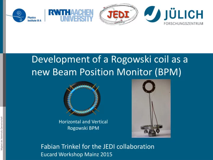
Development of a Rogowski coil as a new Beam Position Monitor (BPM) Mitglied der Helmholtz-Gemeinschaft Horizontal and Vertical Rogowski BPM Fabian Trinkel for the JEDI collaboration Eucard Workshop Mainz 2015 Content Introduction
Mitglied der Helmholtz-Gemeinschaft
28 September 2015 2
Content
- Introduction
- Theory for positon determination with a Rogowski coil as BPM
- Technical approach
- First measurements with a Rogowski coil as horizontal BPM
- Summary and outlook
Mitglied der Helmholtz-Gemeinschaft
28 September 2015 3
Introduction
ο: MDM π: EDM Existence of an EDM violates CP-theorem, which is necessary to explain the matter over antimatter dominance in the Universe Aim of JΓΌlich Electric Dipole moment Investigations collaboration: Measure the EDM of charged hadrons for protons p and deuterons d β = βπ
π π β πΆ β π π π β πΉ
πΈ: β = βπ
π π β πΆ + π π π β π
πΌ: β = βπ
π π β πΆ + π π π β π
Standard Model EDM prediction: 10β32 to 10β31 πππ
Mitglied der Helmholtz-Gemeinschaft
28 September 2015 4
EDM measurements in storage rings
ππ ππ’β π Γ πΉ
π = π
2β π 2πππ
Challenge: Control of the Orbit with a very high accuracy to prevent systematic effects
General idea:
- Inject polarised particles with spin pointing towards the
momentum direction
- βFrozen Spinβ-Technique: without EDM spin stays aligned to
momentum
- EDM couples to electric bending fields
- EDM leads to a polarization build-up in vertical direction
Mitglied der Helmholtz-Gemeinschaft
- 28. September 2015
5
Cooler Synchrotron COSY in JΓΌlich
Polarized Protons / Deuterons Momentum up to 3.5 GeV/c Circumference 184 m EDDA Polarimeter Electron Cooler RF Devices for Spin Manipulations Sextupole magnets Installation of the Rogowski Coil in a Chamber
Mitglied der Helmholtz-Gemeinschaft
28 September 2015 6
Beam Position Monitor (BPM)
BPM measures transverse beam positon (π¦0, π§0) Electrostatic BPM (Standard at COSY): Magnetostatic BPM (New Development): Length β 20 cm Length β 1 cm Excellent response to an RF signal Easy to manufacture Accuracy of the existing COSY BPM system β 0.1 mm Not enough for an EDM measurement More precise position measurement with Rogowski BPM System and a first step to a SQUID-based BPM development
Mitglied der Helmholtz-Gemeinschaft
R
z x y
π 0 π½
7
Rogowski Coil
- 28. September 2015
7
Pickup-Coil to measure the magnetic flux: Standard application to measure AC currents Torus with:
- Major radius π = 40 ππ
- Minor radius π = 5 ππ
- Winding with copper wire π = 1400
- Divided into
- One segment (BCT)
- Two segments
(BPM in one dimension)
- Four segments
(BPM in two dimensions) R a
Mitglied der Helmholtz-Gemeinschaft
- 28. September 2015
8
Magnetic Field of Particle Beam
Model: Pencil-current with constant velocity at position (π¦0, π§0)
Particle Beam Pickup-Coil Current: π½ = π½0 β ππ¨ Position: π
0 =
π¦0 π§0 π = π¦ π§ π¨ Position: Magnetic Field: πΆ = π0
2ππ½
Γ
π βπ 0 π βπ 0 2
Mitglied der Helmholtz-Gemeinschaft
- 28. September 2015
9
Induced Voltage
Taylor of πΆπ to π«(π 0
2 π 2) leads to:
π
πππ,1/1 = ππ½
ππ’ ππ0 π β π2 β π2 π
πππ,1/2 = ππ½
ππ’ π 2 π0 π β π2 β π2 1β
2 π π2βπ2π¦0
π
πππ,1/4 = ππ½
ππ’ π 4 π0 π β π2 β π2 1β
2 2 π π2βπ2π¦0 β
π
2 sin 2Ξ¨β 2π π2
π π2 β π2 3/2 β (π β π2 β π2)
ππππ = β π
ππ’ πΆ β ππ΅
= β π
ππ’ πΆπππ ππ¨πππ
Beam Current Transformator β
β βMutual inductances comparison in Rogowski coil with circular and rectangular cross-sections and its improvementβ http://dx.doi.org/10.1109/ICIEA.2008.4582770
Mitglied der Helmholtz-Gemeinschaft
- 28. September 2015
10
Position Dependency Prediction of a halved Rogowski Coil
Theoretical prediction signal response for a halved coil: Rogowski coil measures the flux density change A voltage is induced and the beam position can be determined by: π¦ β ππ½ππ,ππππ’ β ππ½ππ,π ππβπ’ ππ½ππ,ππππ’ + ππ½ππ,π ππβπ’ Theoretical prediction for position dependency of a halved coil as a horizontal BPM should be independent of the vertical beam position and the other way round
Ξπ1/2 Ξ£π1/2 = 2 π π2 β π2 π¦
(linear for the x direction) (R radius of the coil, a radius of the toroid) R a
π¦ = π π2 β π2 2 Ξπ1/2 Ξ£π1/2
Mitglied der Helmholtz-Gemeinschaft
- 28. September 2015
11
Technical Approach
- 1. Step: Development of a coil with
two segments (BPM in one dimension)
- 2. Step: Development of a coil with
four segments (BPM in horizontal and vertical direction) Development of a testbench and measurements with this coil as an horizontal BPM at COSY Installation of two Rogowski coils as horizontal and vertical BPMs at COSY COSY
Mitglied der Helmholtz-Gemeinschaft
28 September 2015 12
Technical Approach
- 4. Step: Development of a nitrogen or liquid helium cooled coil
with four segments (BPM in vertical and horizontal dimension)
- 5. Step: Development of a SQUID-BPM test bench
COSY
- 3. Step: Characterise the horizontal Rogowski BPM and
the horizontal and vertical Rogowski BPM in the laboratory horizontal Rogowski BPM horizontal & vertical Rogowski BPM
Mitglied der Helmholtz-Gemeinschaft
- 28. September 2015
13
Rogowski BPM for RF Wien Filter
Installation between quadrupoles
- No COSY BPM next to it
- Installation of Rogowski Coil
BPMs at both ends
- Position beam in center
and parallel to Wien Filter E- and B- Field region
Mitglied der Helmholtz-Gemeinschaft
28 September 2015 14
Measurement Setup
- Unpolarised, bunched deuteron beam (N~109),
- Momentum 970 MeV/c, revolution frequency 750 kHz
- Horizontal or vertical orbit bump after 33 seconds
Amplifier (13.5 dB) Amplifier (13.5 dB) Data Acquisition (PC) COSY RF (Reference Signal) Right Left
Mitglied der Helmholtz-Gemeinschaft
28 September 2015 15
Measurement horizontal Displacement
Time Horizontal beam position Fill Bump 1 Displacement 1 Fill Bump 2 Displacement 2
- Measurement of the induced voltages every 4.45 ms for each part of the Rogowski coil
- Create different horizontal orbit bumps with two correctors
- Calculate the displacement as difference of the reference orbit and the orbit bump
Fill Bump 1 Displacement 1 1 Run Cycle 1 Cycle 2
Mitglied der Helmholtz-Gemeinschaft
28 September 2015 16
Analyse Procedure
- 1. Interval
- 2. Interval
Ξ displacement
- Define an interval of 1000 data points (4.45s) for the reference orbit (1.
Interval) and the orbit bump (2. Interval)
- Calculate the Ξdisplacement for each measurement
Preliminary Position determination: π¦ = π π2 β π2 2 Ξπ1/2 Ξ£π1/2 Coil Parameters: R = 40mm a = 5 mm
Mitglied der Helmholtz-Gemeinschaft
28 September 2015 17
Analyse Procedure
Fit function: π + π΅ β sin (2πππ’ + π) Looking for π
- 1. Interval
- 2. Interval
ππ¦,ππππ’πππ = π 2 π2 β π2 1 π2 + π1 2 4π1
2ππ 2 + 4π2 2ππ2 β 3ππ
Fit: ππ β 0.1 ππ (statistical error)
ππ β 0.1 πV
Mitglied der Helmholtz-Gemeinschaft
28 September 2015 18
Beam oscillation or mechanical vibrations?
Beam position oscillation with 6 Hz
- The source of this oscillation
is unknown until now
- With the standard COSY BPM
system it is not possible to disentangle the oscillation
Mitglied der Helmholtz-Gemeinschaft
- 28. September 2015
19
Displacement variation from cycle to cycle
Time Beam position Fill Bump 1 Displacement 1 Fill Bump 1 Displacement 1 Cycle 1 Cycle 2 Ξπ Ξπ = Ξπ2 β Ξπ
1
ππ€ππ = 10 ππ Determine the variation of the displacement from cycle to cycle with constant magnet settings
Mitglied der Helmholtz-Gemeinschaft
- 28. September 2015
20
Varying Horizontal Corrector Strength
Theoretical expectation is consistent with the horizontal orbit measurmenet at the accelerator
ππ¦,π‘π’ππ’ = ππ¦,π‘π’ππ’
2
+ ππ€ππ
2
β 10 ππ Preliminary Slope β512.0 Β± 0.4 ππ/%
Mitglied der Helmholtz-Gemeinschaft
- 28. September 2015
21
Measurement horizontal beam dis- placement in denpendency of a vertical orbit bump
Time
Horizontal beam position
Fill Bump 1 Fill Bump 1 Time
Vertical beam position
Fill Bump 1 Displacement 1 Fill Bump 1 Displacement 1 Measurement of the horizontal beam position Changing the vertical
- rbit position with two
vertical correctors
Mitglied der Helmholtz-Gemeinschaft
- 28. September 2015
22
Horizontal orbit measurement with vertical corrector bump
- 1. Interval
- 2. Interval
Determine the horizontal Ξπππ‘πππππππππ’ between the intervals for the different verical orbit bumps The measured horizontal beam position should be independent of the vertical beam poisition
Mitglied der Helmholtz-Gemeinschaft
- 28. September 2015
23
Horizontal orbit measurement with vertical corrector bump
ππ¦ = ππ¦,π‘π’ππ’
2
+ ππ€ππ
2
β 6 ππ Preliminary
Expectation: no horizontal dependency β small slope, but can be driven from tilts in the magnets or tilt of the coil itself
m = β1.3 Β± 0.4 ππ/% is 3π larger than 0
Mitglied der Helmholtz-Gemeinschaft
- 28. September 2015
24
Summary
Installation of a Rogowski Coil as horizontal BPM in COSY Measurement of the horizontal and vertical beam position dependency
Preliminary Preliminary
π = 512 ππ/% π = β1.3 ππ/%
- An uncooled Rogowski coil worked as an
horizontal BPM in an accelerator enviroment
- The theoretical predictions for an horizontal
BPM have been proven
- The measured sensitivity to the
perpendicular axis is at least 400 times smaller and can be regarded as negligible within the confidence intverval
Mitglied der Helmholtz-Gemeinschaft
28 September 2015 25
Outlook
Characterisation of the horizontal and vertical Rogowski BPMs in the laboratory Installation of a moveable Rogowski coil in COSY
Mitglied der Helmholtz-Gemeinschaft
- 28. September 2015
26
Rogowski Coil Testbench
Installation of the Rogowski coil Movement of the Rogowski coil
Mitglied der Helmholtz-Gemeinschaft
- 28. September 2015
27
Null detector
Changing the postion of the coil in horizontal and certical directon until the beam passes central the coil: 1. Beam βππ£π,ππ Ξ£ππ£π,ππ = 0 βπππππ’,π ππβπ’ Ξ£πππππ’,π ππβπ’ = 0 and Calibration of Referenz Orbit Highest Sensetivity at Coil Centre
Mitglied der Helmholtz-Gemeinschaft
28 September 2015 28
Null detector
Changing the position of the coil in horizontal and vertical direction until the beam passes central the coil: 1. Beam βππ£π,ππ Ξ£ππ£π,ππ = 0 βπππππ’,π ππβπ’ Ξ£πππππ’,π ππβπ’ = 0 and Calibration of referenz orbit Highest sensitivity at coil centre
Mitglied der Helmholtz-Gemeinschaft
28 September 2015 29