
SLIDE 1
6-7-2009
Challenge the future
Delft University of Technology
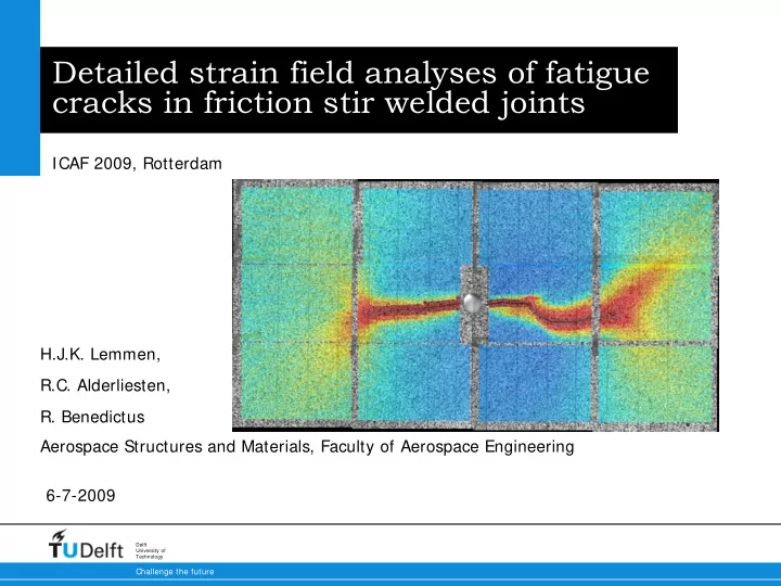
Detailed strain field analyses of fatigue cracks in friction stir welded joints
H.J.K. Lemmen, R.C. Alderliesten,
- R. Benedictus
ICAF 2009, Rotterdam Aerospace Structures and Materials, Faculty of Aerospace Engineering