
SLIDE 1
Cylinder Theory Derivation Andrew Ning We will find the stress in a - - PDF document
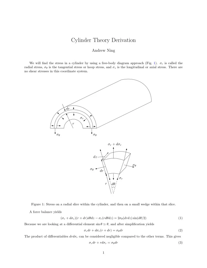
Cylinder Theory Derivation Andrew Ning We will find the stress in a cylinder by using a free-body diagram approach (Fig. 1). r is called the radial stress, is the tangential stress or hoop stress, and z is the longitudinal or axial
i
i − por2
i
i r2
i
i − por2
i r2
i
i − por2
i r2
i
i − por2
i )
i − por2
i