CREEP OF FULLY OR PARTIALLY FRP-CONFINED SQUARE OR CIRCULAR CONCRETE - - PDF document

creep of fully or partially frp confined square or
SMART_READER_LITE
LIVE PREVIEW

CREEP OF FULLY OR PARTIALLY FRP-CONFINED SQUARE OR CIRCULAR CONCRETE - - PDF document

18 TH INTERNATIONAL CONFERENCE ON COMPOSITE MATERIALS CREEP OF FULLY OR PARTIALLY FRP-CONFINED SQUARE OR CIRCULAR CONCRETE COLUMNS Y. S. Ma, Y. F. Wang*, B. Han, M. H. Liu School of Civil Engineering , Beijing Jiaotong University , Beijing ,


slide-1
SLIDE 1

18TH INTERNATIONAL CONFERENCE ON COMPOSITE MATERIALS

1 Introduction Externally wrapping fiber-reinforced polymer (FRP) composites around concrete columns has found increasingly wide applications in strengthening and retrofitting of existing concrete structures. As demonstrated by extensive published studies, the uses of FRP jackets, hoops and spirals for transverse confinement are all particularly suited for gaining better short-term behaviors of concrete columns under axial compressive loading, which involve the concrete compressive strength, ultimate compressive strain and ductility capacity [1, 2]. However, few investigations [3, 4] are related to the creep behavior

  • f FRP wrapped concrete columns (FWCCs), with

the limitations as: the loading process is not long enough for developing creep fully; the concerned confining materials are glass FRP (GFRP) and carbon FRP (CFRP), without aramid FRP (AFRP); the confining form involved is only FRP jackets; square or rectangular columns confined with FRP have not yet been tested for creep; and the influence

  • f concrete composition and strength can’t be

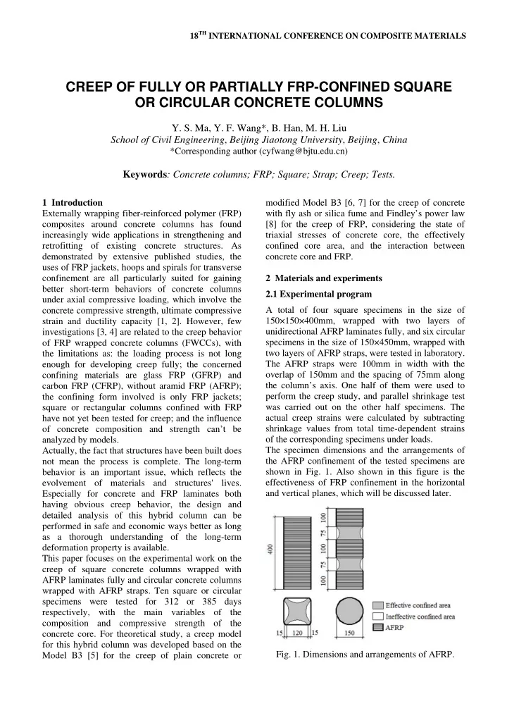
analyzed by models. Actually, the fact that structures have been built does not mean the process is complete. The long-term behavior is an important issue, which reflects the evolvement of materials and structures' lives. Especially for concrete and FRP laminates both having obvious creep behavior, the design and detailed analysis of this hybrid column can be performed in safe and economic ways better as long as a thorough understanding of the long-term deformation property is available. This paper focuses on the experimental work on the creep of square concrete columns wrapped with AFRP laminates fully and circular concrete columns wrapped with AFRP straps. Ten square or circular specimens were tested for 312 or 385 days respectively, with the main variables of the composition and compressive strength of the concrete core. For theoretical study, a creep model for this hybrid column was developed based on the Model B3 [5] for the creep of plain concrete or modified Model B3 [6, 7] for the creep of concrete with fly ash or silica fume and Findley’s power law [8] for the creep of FRP, considering the state of triaxial stresses of concrete core, the effectively confined core area, and the interaction between concrete core and FRP. 2 Materials and experiments 2.1 Experimental program A total of four square specimens in the size of 150×150×400mm, wrapped with two layers of unidirectional AFRP laminates fully, and six circular specimens in the size of 150×450mm, wrapped with two layers of AFRP straps, were tested in laboratory. The AFRP straps were 100mm in width with the

  • verlap of 150mm and the spacing of 75mm along

the column’s axis. One half of them were used to perform the creep study, and parallel shrinkage test was carried out on the other half specimens. The actual creep strains were calculated by subtracting shrinkage values from total time-dependent strains

  • f the corresponding specimens under loads.

The specimen dimensions and the arrangements of the AFRP confinement of the tested specimens are shown in Fig. 1. Also shown in this figure is the effectiveness of FRP confinement in the horizontal and vertical planes, which will be discussed later.

  • Fig. 1. Dimensions and arrangements of AFRP.

CREEP OF FULLY OR PARTIALLY FRP-CONFINED SQUARE OR CIRCULAR CONCRETE COLUMNS

  • Y. S. Ma, Y. F. Wang*, B. Han, M. H. Liu

School of Civil Engineering, Beijing Jiaotong University, Beijing, China

*Corresponding author (cyfwang@bjtu.edu.cn)

Keywords: Concrete columns; FRP; Square; Strap; Creep; Tests.

slide-2
SLIDE 2

The test variables in this experiment were the composition and compressive strength of the concrete core. Five concrete batches, labeled A, B, C, D and E, were used. Correspondingly, the creep specimens were named as FWCC-A, FWCC-B, FWCC-C, FWCC-D and FWCC-E. The summary of the specimen test matrix is given in Table 1. 2.2 Materials and properties The cementitious materials of concrete core used in the test were ordinary Portland cement, fly ash and silica fume. River sand was used as the fine aggregate and crushed granite stone with a maximum size of 40mm was used as the coarse

  • aggregate. The densities of the fine and coarse

aggregate were 2.65×10³kg/m3 and 2.74×10³kg/m3

  • respectively. The composition and compressive

strength of the concrete are shown in Table 2, where the compressive strength was determined based on the average measurement of three identical 100mm concrete cubes from the same batch. The AFRP laminates were used for transverse confinement, and epoxy resin was used as adhesive. The elastic modulus, ultimate tensile strain and thickness per layer of the AFRP laminate given by manufacturer are 118000MPa, 0.017 and 0.286mm respectively. 2.3 Testing procedure and instrumentation The concrete mix was slowly poured into the steel moulds by vibration, to prevent segregation and voids from forming. Specific attention was paid to the corner zones of square specimens so that good compaction was ensured at the corners. Slump tests were taken on site to check the quality of the concrete used. One day after casting, the concrete columns were demolded and cured in a controlled environment of 20±2℃ and relative humidity > 95% for 20 days. Meanwhile, three cubes were prepared for each group and cured in the same manner as the column specimens to measure the concrete compressive strength at 28 days. Before wrapping the AFRP laminates, square specimens were rounded off to have the corner radius of 15mm with a grinding machine to avoid local stress concentration. The AFRP laminates were wrapped fully or discretely around the columns in a wet lay-up process, with the main fibers orientated in the hoop direction of the columns. Effective joints were attained by overlapping the laminates 150mm in length. The hybrid columns were then cured for 8 days, with a controlled temperature of 20±2℃ and a relative humidity of 95% above. For measuring the deformation, each creep specimen was instrumented at its mid-height with an embedded vibrating wire strain gauge (DI-25) in the axial direction. The gauges were then connected to an automated data acquisition system. The same gauges were also embedded in the other five companion specimens that remained unloaded to correct for non-creep related deformations. At the age of 28 days, the creep specimens were subjected to sustained axial stresses corresponding to the stress-strength ratio of 30% for 312 or 385

  • days. Shrinkage was tested parallel to creep. All

creep and shrinkage specimens were kept in a controlled temperature of 20℃ throughout the test. Table 1. Specimen test matrix Specimen Cross-section Dimension (mm) Confinement type Applied stress (MPa) No. of specimens FWCC-A Square 150150400 Fully 9.5 2 FWCC-B Square 150150400 Fully 9.5 2 FWCC-C Circular 150450 Partially 15.1 2 FWCC-D Circular 150450 Partially 21.0 2 FWCC-E Circular 150450 Partially 21.0 2 Table 2. Composition and properties of concrete Composition (kg/m3) Concrete Measured 28-day cubic compressive strength (MPa) Slump (mm) Cement Fly ash Silica fume Water Sand Coarse aggregate A 47.3 37 229.5 40.5 105 765.00 1360.00 B 51.1 37 246.5 43.5 105 758.90 1349.10 C 65.9 37 394.7 150 749.87 1124.80 D 73.0 37 451.6 79.69 170 760.44 929.43 E 76.2 37 470.5 83.04 155 727.45 964.30

slide-3
SLIDE 3

CREEP OF FULLY OR PARTIALLY FRP-CONFINED SQUARE OR CIRCULAR CONCRETE COLUMNS

3 Analytical model In this section, the creep analyses are presented for the square concrete columns wrapped with FRP laminates fully and circular concrete columns wrapped with FRP straps. These creep analyses follow the analogy for circular concrete columns wrapped with FRP laminates fully. However, the differences in the cross-sectional shape and confining form lead to the differences in the distribution of confining stress and the property of

  • deformation. Therefore, specialized treatments for

the two kinds of FRP-confined column are presented

  • first. Then the modeling approach is elaborated.

3.1 Fully FRP-confined square concrete columns The application of FRP confinement improves both compressive strength and ductility of square columns, but influenced strongly by the shape of cross-section, to a lower degree than that of circular

  • columns. Different from circular columns, square

columns can not mobilize the FRP confining pressure on their flat sides when the axial strains are

  • small. As the lateral deformation of columns

increases, the sides of FRP sheets have the tendency to bend outward, providing a small, increasing confining pressure. However, lateral confining pressures are still exerted on a section mainly through its four corners because of the low flexural stiffness of the FRP wraps. Therefore, the distribution of confining stress is not uniform along the sides of cross-section and arching action is assumed to act in the form of second-degree parabolas, as illustrated in Fig. 1. To determine the lateral confining pressure, the square cross-section is transformed into a circular cross-section by taking its side length L as the diameter Deq of the equivalent concrete cylinder and keeping its FRP-concrete volumetric ratio the same to that of the equivalent FRP-confined cylindrical column as

f f f c eq

4 4 V t t V L D     (1) where  = FRP-concrete volumetric ratio; Vf and Vc = volumes of FRP and concrete core respectively (mm3); tf = thickness of FRP (mm); L = side length

  • f square section (mm); and Deq = diameter of the

equivalent concrete cylinder (mm). Utilizing the concept of equivalent cylinder and the unchanged FRP-concrete volumetric ratio, the lateral confining pressure p on the square concrete core can be given as

f f f eq

2 2 t p D      (2) where

f

 = stress in FRP (MPa). 3.2 Partially FRP-confined circular concrete columns The confining stress from FRP straps is activated by the lateral deformation of concrete in response to the applied axial compressive load and is closely related to the spacing of the transverse reinforcements. Apparently, the resulting confining stress is not constant along the axial axis of the column and is qualitatively assumed to have its lowest value at the mid-section between adjacent straps. To find an assumed uniformly distributed pressure

  • ver the surface of the concrete core, the effective

confining pressure, similar to that used by Sheikh and Uzumeri [9] and Mander et al. [10], was introduced into the concrete columns confined by FRP straps [11] based on arch action between FRP straps in vertical plane, as illustrated in Fig. 1. The physical connotation of the uniform lateral confining pressure is that of a concrete column, which is confined by a uniform equivalent FRP-jacket that replaces the discrete FRP-straps [12]. On the basis of the FRP-concrete volumetric ratios being identical for the original and equivalent columns, the FRP thickness of the equivalent confined cylindrical column can be calculated as

eq f

ns t t H  (3) where teq = equivalent thickness of FRP (mm); n = number of FRP straps; s = width of one FRP strap (mm); H = height of column (mm). Therefore, the lateral confining pressure p on the partially FRP- confined circular concrete core is

eq f f

2 2 t p D      (4) where D = diameter of concrete column (mm). 3.3 Modeling the creep of concrete columns confined by FRP By utilizing the equivalent diameter or thickness, the creep analysis for these two kinds of FRP-confined concrete columns follows the analogy of that for circular concrete columns wrapped with FRP jacket, in which creep models for concrete and FRP are incorporated into mechanical equilibrium and strain

slide-4
SLIDE 4

compatibility for the composite section, considering the confinement effect. Creep analysis in this paper involves Model B3 for plain concrete [5] or the modified Model B3 for concrete with fly ash [6] or silica fume [7], the power law for FRP creep [8], the effective creep Poisson’s ratio of concrete [13] and the calculating approach for the creep of concrete under triaxial variable stress [14] and the creep of FRP under uniaxial variable stress [8]. Details of the creep analysis for FRP-confined concrete columns are elaborated in [6, 7].

  • 4. Results and discussions

4.1 Experimental results

  • Fig. 2 presents the creep compliance J(t, t’), which is

taken as elastic plus creep strain at age t caused by a unit constant stress applied at age t', of the fully FRP-confined square concrete columns FWCC-A and FWCC-B. The letters A and B in this figure mark the types of the concrete used in the specimens. Clearly, the creep development becomes quite slow after about 100 days, which results from the fly ash included in the concretes as a partial replacement of

  • cement. The final tested creep coefficients, defined

as the ratio of the net creep strains to the initial elastic strains, of FWCC-A and FWCC-B are 0.61 and 0.58 respectively. Also shown in this figure are the test results of fully FRP-confined circular concrete columns reported in [6]. The materials of concrete core and FRP jacket are all identical for the corresponding square and circular specimens. The only difference between them is the cross-sectional shape. The final creep coefficients of the circular specimens, measured as 0.66 and 0.68, are slightly higher than those of the corresponding square specimens.

  • Fig. 2. Creep of fully confined concrete columns.

From Fig. 2, it can be seen that the shape effect is not evident on the creep behavior of FRP-confined

  • columns. The curves of square specimens are rather

close to those of circular specimens with the same

  • concrete. For concretes A and B, the average

differences are 3.96% and 4.77% between circular and square specimens. In addition, with the same concrete A, the creep compliance of the circular specimen is generally lower than that of the square specimen; while the situation for concrete B is totally converse. This implies that the sectional shape does not affect their creep regularly.

  • Fig. 3 displays the creep compliance of the partially

FRP-confined circular concrete columns FWCC-C, FWCC-D and FWCC-E. The different concretes are labeled with C, D and E in this figure. Because concrete C is plain concrete while concretes D and E contain silica fume as a supplementary binder, which has a restraining effect on the development of concrete creep [15, 16], the creep growth of FWCC- C tends much faster than those of FWCC-D and FWCC-E, and keeps a considerable upward tendency even at the age of 400 days. The final tested creep coefficients of FWCC-C, FWCC-D and FWCC-E are 0.94, 0.63 and 0.61 respectively. To examine the effect of partial confinement on creep behavior, creep compliance of fully FRP- confined circular high strength concrete columns, details of which are presented in [7], are also given in Fig. 3. All parameters, including concrete and FRP materials and dimensions, are totally identical for the corresponding fully and partially confined specimens except the confining form and so-induced FRP-concrete volumetric ratio. However, there is no corresponding fully confined specimen for concrete C and the creep test for concrete E confined with FRP jackets has to be concluded at the age of 245 days due to an instrumental problem.

  • Fig. 3. Creep of confined circular concrete columns.
slide-5
SLIDE 5

5 CREEP OF FULLY OR PARTIALLY FRP-CONFINED SQUARE OR CIRCULAR CONCRETE COLUMNS

It is clear from this figure that confining form affects the creep of this kind of hybrid columns slightly. For concretes D and E, the curves of partially and fully confined specimens are very close to each other, with the average differences of 1.29% and 3.56% respectively. 4.2 Analytical results

  • Figs. 4 and 5 show the comparisons between the

tested and calculated results of FWCC-A, FWCC-B, FWCC-C, FWCC-D and FWCC-E respectively. It is clear that the model developed in this paper for the creep of fully or partially FRP-confined square or circular concrete columns provides predictions very close to the measured data. The average differences between the predicted and tested values for FWCC- A, FWCC-B, FWCC-C, FWCC-D and FWCC-E are 1.57%, 0.90%, 2.10%, 0.99% and 1.63% during the entire loading process, which are quite acceptable for creep experiments.

  • Fig. 4. Model verification for fully FRP-confined

square concrete columns.

  • Fig. 5. Model verification for partially FRP-confined

circular concrete columns.

  • 5. Conclusions

From the experimental and theoretical results in this paper, we can draw the following conclusions: (1) Cross-sectional shape and confining form have a negligible effect on the creep of FRP-confined concrete columns. Generally, fully or partially FRP- confined square or circular concrete columns creep fairly closely to the corresponding fully FRP- confined circular concrete columns with the same concrete mix. (2) The creep model of fully or partially FRP- confined square or circular concrete columns developed in this paper, based on the B3 Model for the creep of plain concrete or the modified B3 Model for the creep of concrete with fly ash or silica fume, and the power law for the creep of FRP, is in good agreement with the test data, with average errors of less than 2.10%. (3) The approach of transforming the fully or partially FRP-confined square or circular concrete columns into the fully FRP-confined circular concrete columns with the equivalent concrete diameter or FRP thickness and the same FRP- concrete volumetric ratios is feasible. Acknowledgements The authors would like to acknowledge the financial support of the New-Century Training Programme for Talents by the Ministry of Education of China under grant No. NCET-04-0097. The contribution of FRP materials from Shenzhen Ocean Power Engineering Technology Co., Ltd. is also gratefully acknowledged. References

[1] H. Saadatmanesh, M. R. Ehsani and M. W. Li “Strength and ductility of concrete columns externally reinforced with fiber composite straps”. ACI Structural Journal, Vol. 91, No. 4, pp 434-447, 1994. [2] J. G. Teng, J. F. Chen, S. T. Smith and L. Lam “FRP strengthened RC structures”. John Wiley & Sons, Inc., 2002. [3] W. Naguib and A. Mirmiran “Creep analysis of axially loaded fiber reinforced polymer-confined concrete columns”. Journal of Engineering Mechanics, Vol. 129,

  • No. 11, pp 1308-1319, 2003.

[4] Q. Yu, L. H. Han and Z. Zhang “Long-term effect in FRP-confined concrete stub columns under sustained loading”. China Journal of Highway and Transport, Vol. 16, No. 3, pp 58-63, 2003. [5] Z. P. Bažant and S. Baweja “Creep and shrinkage prediction model for analysis and design of concrete structures: Model B3”. Adam Neville Symposium: Creep

slide-6
SLIDE 6

and Shrinkage—Structural Design Effects, Michigan, pp 1-83, 2000. [6] Y. F. Wang, Y. S. Ma and L. Zhou “Creep of FRP- wrapped concrete columns with or without fly ash under axial load”. Construction and Building Materials, Vol. 25,

  • No. 2, pp 697-704, 2010.

[7] Y. S. Ma and Y. F. Wang “Creep of AFRP confined high-strength concrete columns under low-level stress”. Submitted to Advances in Structural Engineering. [8] W. N. Findley “Mechanism and mechanics of creep of plastics”. SPE Journal, Vol. 16, No. 1, pp 57-65, 1960. [9] S. A. Sheikh and S. M. Uzumeri “Analytical model for concrete confinement in tied columns”. Journal of Structural Engineering, Vol. 108, No. 12, pp 2703-2722, 1982. [10] J. B. Mander, M. J. N. Priestley and R. J. T. Park “Theoretical stress-strain model for confined concrete”. Journal of Structural Engineering, Vol. 114, No. 8, pp 1804-1826, 1988. [11] H. Saadatmanesh, M. R. Ehsani and M. W. Li “Strength and ductility of concrete columns externally reinforced with fiber composite straps”. ACI Structural Journal, Vol. 91, No. 4, pp 434-447, 1994. [12] R. Eid and A. N. Dancygier “Confinement effectiveness in circular concrete columns”. Engineering Structures, Vol. 28, No. 13, pp 1885-1896, 2006. [13] I. J. Jordaan and J. M. Illston ‘‘Time-dependent strains in sealed concrete under multiaxial compressive stress’’. Magazine of Concrete Research, Vol. 23, No. 75- 76, pp 79-88, 1971. [14] K. S. Gopalakrishnan, A. M. Neville and A. Ghali ‘‘A hypothesis on mechanism creep of concrete with reference to multiaxial compression’’. ACI Journal Proceedings, Vol. 67, No. 1, pp 29-35, 1970. [15] B. Persson “Quasi-instantaneous and long-term deformations of high performance concrete with sealed curing”. Advanced Cement Based Materials, Vol. 8, No. 1, pp 1-16, 1998. [16] M. Mazloom, A. A. Ramezanianpour and J. J. Brooks “Effect of silica fume on mechanical properties of high- strength concrete”. Cement and Concrete Composites, Vol. 26, No. 4, pp 347-357, 2004.