
SLIDE 1
18TH INTERNATIONAL CONFERENCE ON COMPOSITE MATERIALS
MECHANICAL BEHAVIOUR OF FRP-CONFINED CONCRETE COLUMNS UNDER AXIAL COMPRESSIVE LOAD
V.Tamužs*, V.Valdmanis Institute of Polymer Mechanics, University of Latvia, 23 Aizkraukles St., Riga, LV-1006, Latvia,
*tamuzs@pmi.lv
Keywords: Concrete columns, composite confinement, strength, deformability, stability
Abstract The strength, deformability and stability of concrete columns confined by carbon composite sheets is considered at axial compressive loading. The formulas for prediction of ultimate strength, ultimate strain, and the tangent modulus above the limit of nonlinearity are given. Confined reinforced concrete columns also are considered. The loss of stability of columns above the strength
- f plain concrete is analyzed and it is proved that
FRP confinement is efficient only for columns having low or moderate slenderness (λ<40). Fiber-reinforced polymer composites have found wide applications in the civil engineering due to their high corrosion resistance and the ease of
- application. One important application of the fiber-
reinforced composites is as confinement of the concrete columns to enhance the strength and
- ductility. Such confinement can be used when the
strength of concrete structure should be improved (for damaged structures or for increased service load). It is well observed by many researchers that the confined concrete above the ultimate compressive strength of the plain concrete
co
f
continues to carry the increased load, but in the bilinear manner with a second tangent modulus
1 2
E E <<
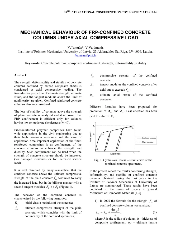
(Figure 1). The behavior
- f
the confined concrete is characterized by the following quantities:
1
E
initial elastic modulus of the concrete;
co
f
ultimate compressive strength of the plain concrete, which coincides with the limit of nonlinearity of the confined specimens;
cc
f
compressive strength
- f
the confined concrete;
2
E
tangent modulus the confined concrete after axial stress exceeds
co
f
;
ε cc
ultimate axial strain of the confined concrete. Different formulas have been proposed for prediction of
cc
σ
and
cc
ε
. Less attention has been paid to value of
2
E .
- Fig. 1. Cyclic axial stress – strain curve of the
confined concrete specimens. In the present report the results concerning strength, deformability, and stability of confined concrete columns obtained during the last years in the Institute of Polymer Mechanics of University of Latvia are summarized. These results have been published in the series of papers in journal Mechanics of Composite Materials [1-6]. 1) In 2006 the formula for the strength
cc
f of
confined concrete column was analyzed:
R h f f
ju co cc